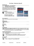
Transcription of AIRFED 2000 - Anest Iwata
1 IMPORTANTThe AIRFED protection mask kit is a compressed air fed respirator which, when supplied with breathable quality compressed air,passes it via a belt-mounted regulator and flexible tube into a visor. The regulator is fitted with a replacement nuisance odour fil-ter. These instruction must be read in full before operating the to follow these instructions completely may result in a decrease in protection or no protection at misuse or handling other than those indicated in this Instruction Manual is not covered by guarantee. ANESTIWATA disclaims all responsibility for any accident or damage caused by failure to observe the operational and safetyprocedures as from this manual.
2 In the interest of user friendliness, this manual contains information in a brief and con-cise any additional information you may require regarding equipment operations, or if any missing parts or any damageduring transportation is found, please contact your nearest Anest Iwata Company (see last cover page).Manuale d Istruzione d Uso e ManutenzionePROTECTION MASKAIRFED 2000 DESCRIPTIONB rowguard and vizorCover for vizorWaistbeltPre-set air regulatorCarbon filterGun hose fittings 1,25 mThis visor system conforms to provisional European Standard prEN 1835:1995 Specification for light duty Compressed air brathing apparatus incorporating helmets or hoods APPLICATIONThe AIRFED system will provide protection against airborn dusts, mists, gases and vapours.
3 This system offers respiratory pro-tection to class LDH 3 and hence offers a protection factor of up to 200. This means that it can be used in areas where the con-centration of contaminant in the workplace air is up to 200 times the Occupational Exposure Limit ( )- This system should not be used where the level of contaminant exceeds 200 x the or where the contaminant or itslevel is This system should not be used in oxgen deficient This system should not be used below 0 FLOW INDICATOR (AFI) TROUBLESHOOTINGIf the AFI indicates a drop in air flow (refer to ), perform the following check under uncontaminated condi-tions:- Ensure that the compressed air supply is turned on at the wall and that imput pressure is correctly Check the security of the rigid air flow indicator tube positioned in the visor.
4 If it has come loose from the end of the flexible transparent hose, push it back into Make sure that the transparent breathing hose is not kinked, blocked or If there is a failure or suspected failure of the regulator, it should be returned to the Anest Iwata for test, rectification PARTS:- Replacement visor Replacement :- To external surfaces of all components may be cleaned using a sponge and warm soapy water and afterwards rinsed and allowed to dry Do not immerse any part of the system in water, particulary the regulator system as this may damage :- The equipment should be stored in an uncontaminated environment away from direct sunlight preferably packed in Recommended limitis of storage are -10 to +50 with RH<60% SIGNIFICATO DEI MARCHI:- CE(1) 1F3 to EN166- (1) = Manufactures mark- 1 = Optical class 1- F = Increased Robustness - 3 = Resistance to chemical splash- Regulator CE 0086 prEN1835 19950086 = Notified body- prEN1836 1195 = Standard to which the product conformsBefore use, adjustment or maintenance, it isimportant to read this instruction manual verycarefully.
5 This manual must be stored in a safe place forany future reference that may be necessary. GBANEST Iwata Italia , Corso Vigevano 10155, Torino (Italy)Tel. diretto +39 011 - 24 80 868 - Fax +39 011 - 85 19 Iwata Europe ESPA A Y Maresme, 44-46 Planta 2 OF. 25 / 08918 - Badalona(Barcelona)Tel.:+34 933 20 59 93 - Fax.:+34 933 20 55 64 Iwata Europe DEUTSCHLANDDorf ckerstr. 25, 74248 EllhofenTelefon: +49 (0)7134- 917368 - Fax: +49 (0)7134 - 917378 Handy: +49 (0)172 - 62 74 Iwata Europe , Corso Vigevano 10155, Torino ItalyDirect Tel. +39 011 - 24 80 868 Fax +39 011 - 22 74 Iwata Scandinavia AB. g rdesv gen 6C, 433 30 PARTILLE Tel. +46 (0)31 - 340 28 60 - Fax +46 (0)31 - 340 28 Iwata France rue de Madrid - BP 7405 38074 St Quentin FallavierT l.
6 +33 (0)4 - 74 94 59 69 - Fax +33 (0)4 - 74 94 34 Iwata 10 Little End Road - Eaton SoconSt. Neots - CAMBRIDGESHIREPE19 8JH Tel.: +44 (0) 1480 405419 Fax: +44 (0) 1480 Sales Branches:g. If spray gun is to be used, connect spray gun to the spray Check the air quality from the visor. If any odour is detectable then the carbon filter should be replaced.(See mainte-nance section for details on replacing the filter). If an odour is still detected then the visor should not be used. The cause should then be investigated since further prefiltering will probably be If an accessory such as spray gun or power tool is to be driven from the same compressed air supply tube, ensure that the airflow indicators shows that sufficient flow is being delivered into the visor when the accessory is consuming the maximum airflow THE VISOR ASSEMBLY.
7 The users should be trained in correct fitting of the visor assembly- Open out the head harness by rotating the knob on the back of the To fit the head harness, adjust the crown strap and the knob at the back of the head harness until the foam face seal fits around the face when the visor is flipped The light duty breathing hose should run down the back of the USE:The operators should be trained in the use of this equipment prior to entering a hazardous If an oil odour develops during use the quality of the supply and carbon filter should be checked to ensure that the air being fed to the breathing eqipment is free from oil.
8 - If the face seal does not fit closely to the face than the stated levels of protection may not be This system should not be used below 0 This system should not be used in or with oxygen or oxygen riched At very high work rates the pressure in the visor may become negative at peack inhalation The protection factor may not be achieved with persons with eccessive facial hair or The user must ensure the purity and identity of the breathing air supply at all Adequate protection may be provided by the apparetus in certain highly toxic This apparatus should not be used in area where inhalation of the atmosphere, whilst escaping in the event of failureof the air supply, would cause serious harm to The air supply system should be equipped with an appropriately rated and adjusted pressure relief safety The optical class of the visor may be reduced by adding one or more visor AND MAINTENANCE:All maintenance should be performed in an uncontaminated The carbon filter may be replaced by, with the air turned off, unscrewing the bowl below the regulator and grasping the filter, firmly twist and pull downwards.
9 The old filter should be disposed of. A new filter is fitted by inserting and twi-sting upwards. The bowl should then be refitted and screwed tigthly to the Visor covers (should be replaced when contamination start to obscure vision by pulling off and pushing a new visor cover over the two metal It is recommended that the complete kit of the equipment is inspected on a mountly basis (or before use for occasio-nal user) and any worn or damage components are replaced. Particular attention should be paied to the visor and its foam The carbon filter shelf life from the date of manifacture. Expiry date should be The equipment ( other than the carbon filter) has a shelf life of 5 years from manufacturing supply specification- Imput pressue consumption 140 l/min- consumption 300 l/minNOTE: The air supply must be of breathable quality as defined in EN 132.)
10 The air supply system should beequipped with a pressure relief safety SUPPLY HOSE SPECIFICATIONThe system should be used with a 5/16 supply hose with maximum working pressure of 15 bar and maximum length of10 AIR SUPPLY SPECIFICATION AND AIR FLOW INDICATORMINIMUM DESIGN FLOWRATE: 140 air -flow indicator (AFI) is positioned in the visor on the left-hand edge of the wearer s field of vision. When the flow ofair drops below the minimum design flowrate quoted above, the float will just break the upper edge of the opaque portionof the tube (refer to fig. 1). If a drop in air flow is indicated in this way, perform the checks listed below under Air flowindicator troubleshooting.