Transcription of AIRTRONIC D2/D4 DIAGNOSTIC AND REPAIR …
1 A IRTRONI C D2/D4 . D IAG NOSTIC AND REPAIR MANU A L. A WORLD OF COMFORT. Table of Contents REVISION LEVEL A - 12/09/13. Chapter Content Page 1 System Overview .. 3. 2 DIAGNOSTIC Devices .. 4. 3 Visual Inspection .. 6. 4 Maintenance / Troubleshooting & REPAIR .. 11. 5 Service Information .. 19. 6 Parts Breakdown .. 26. 7 Fuel Filter / Fuel Pump Angle .. 32. PLEASE NOTE! The EW14 Warranty Process requires Edith extraction printouts to record codes before proceeding with repairs and after the REPAIR steps listed in this manual are completed . For your warranty claim to be paid you must document the Complaint, Cause and Correction steps in your warranty claim write-up . CAUTION: Indicates that personal injury or damage to equipment may occur unless specific guidelines are followed. DANGER: Indicates that serious or fatal injury may result if specific guidelines are not followed.
2 This document aims to support service technicians and end users in North America. This does not replace documentation produced by J. Ebersp cher. The installation instructions and standards described in this document are NOT APPLICABLE TO MARINE INSTALLATIONS. Please consult a certified Espar Marine dealer for marine installation. This publication was correct at the time of going to print. However, Espar Inc. has a policy of continuous improvement and reserves the right to amend any specifications without prior notice. 2. 1 System Overview REVISION LEVEL A - 12/09/13. SYSTEM OVERVIEW. The Espar AIRTRONIC D2 heater is designed to lower idling by providing an alternative in cab heat solution SYSTEM OPERATION. 1. The operation turns on the device via either the Mini, Digi or Digi-Max Controller.
3 A. The Mini-Controller has a simple rheostat design for cab temperature control (Figure 1). b. The Digi/Digi-Max Controller are digital devices that controls the cab temperature and also acts as a DIAGNOSTIC device (Figure 2 & 3). PLEASE NOTE! If the unit is equipped with a Digi-Controller and the display is showing H, the interior temp of the unit is too high to allow the Espar unit to operate. If the display is showing L, the unit will work but the temp is too cold to show the correct temp on the display. Figure 1 Figure 2 Figure 3. 2. When the heater is first started the following events take place: a. The unit runs through a 3 second DIAGNOSTIC check. b. The fan and glow pin come on. c. After 60 seconds the fuel pump starts pumping fuel. d. If the unit doesn't fire within 2 1/2 minutes: I.
4 The unit will then stop the fuel pump and pause for 60 seconds. II. The unit will then attempt a second start. e. If the unit doesn't fire after the second attempt, a code 52 will be set. Refer to the fault code section of this document for proper troubleshooting. PLEASE NOTE! Times are approximate, it is more important to understand there are 2 attempts and the process can takes some time. After the second failed attempt, the heater fan motor will remain on for up to three minutes which is normal and part of the logic of the heater. The unit must be allowed time to run through its cycle. If there is an issue it will trip a code. 3. Inside the unit a. The fan provides air flow through the combustion chamber and the ventilation hole. b. The glow pin heats the atomizer chamber to preheat in preparation for fuel.
5 C. Fuel first enters below the ventilation hole. d. It is then atomized and ignites. e. The flame burns through the combustion chamber. f. The flame sensor recognizes a temperature rise and then shuts off the glow pin. g. The ECU measures the cab temperature via the return air temperature sensor in correlation with the set point (Figure 4). h. Units utilizing the Digi/Digi-Max Controller do not utilize the return air temp sensor but instead use the remote air temperature sensor on the Controller (Figure 2 & 3 page 3). i. The unit switches between boost, high, medium, low and standby. I. When it first ignites it is always in boost. II. Mode is controlled via fuel pump frequency and fan speed. 3. 1 System Overview REVISION LEVEL A - 12/09/13. SYSTEM OVERVIEW. 4. Difference by controller operation a.
6 When operating in standby mode with a Mini-Controller the fan will PLEASE NOTE! continue to run in order to maintain airflow across the return air Any component replacement will require the serial number of the espar unit temperature sensor. be entered in order to charge the component to the work order. The seial b. When operating in standby mode with a Digi/Digi-Max Controller the number is located on the side of the Espar unit (Figure 5). fan will shut down as air flow is not required. Serial number Figure 4 Figure 5. Direction of air flow Ventilation hole Glow pin Flame sensor Combustion chamber Fuel pump Figure 6. 4. 2 DIAGNOSTIC Devices REVISION LEVEL A - 12/09/13. MULTIPLE DIAGNOSTIC DEVICES ARE AVAILABLE AS OUTLINED BELOW: This manual is designed to be used with the AIRTRONIC D2/D4 .
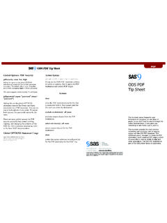
7 Please reference the data tag on your heater to verify which heater model you have. The AIRTRONIC D2/D4 can utilize any of the fault code readers listed here. 1. EDITH PC BASED diagnostics PREFERRED : The ability to print out an ECU extraction is only available using EDITH PC. diagnostics , and is a requirement for taking advantage of the EW14 express warranty protocols. Full product testing capability including remote running of system components without removal of the heater, can be utilized for rapid fuel system priming. EDITH. Figure 7. 2. DIGI- DIAGNOSTIC TOOL. Inexpensive - basic code viewing & clearing functions. While there are other fault code readers available, in this manual we are going to focus on only two methods Edith PC diagnostics and the Digi-Controller (controller installed with the heater) / Digi- DIAGNOSTIC Tool (identical handheld tool).
8 Figure 8. 5. 2 DIAGNOSTIC Devices REVISION LEVEL A - 12/09/13. EDITH PC diagnostics PREFERRED . Figure 9. 6. 2 DIAGNOSTIC Devices REVISION LEVEL A - 12/09/13. 2. DIGI- DIAGNOSTIC TOOL/CONTROLLER. 1. First turn the controller on by pressing and releasing the instant ON /. OFF key. 2. To review fault codes press and hold the instant ON/OFF until the display shows da . a. Codes will be displayed in the following manner: 1. F0 will display first followed by the code number. 2. This is the active code and is the code that should be repaired first. a. Subsequent codes will be display with F1, F2, F3 etc. followed by the code number. 3. The F1 simply indicates this is the first or most recent historical code and they go in order. 4. If there is not driver complaint, no active code, and the system is operating no repairs are needed codes should be cleared.
9 5. To clear fault codes: a. While in DIAGNOSTIC mode push and hold both arrow buttons until EE is displayed on the screen. b. To exit DIAGNOSTIC mode hit the ON / OFF button. c. To shut the unit down hit the ON / OFF button again. PLEASE NOTE! ALWAYS document codes prior to clearing them - EVEN if no repairs are made. Figure 10. PLEASE NOTE! Prior to making repairs ALWAYS complete a visual inspection / operation inspection and note findings in the work performed section of your REPAIR order. PLEASE NOTE! Any component replacement will require the serial number of the espar unit be entered in order to charge the component to the work order. 7. 3 Visual Inspection REVISION LEVEL A - 12/09/13. VISUAL INSPECTION. 1. Complete a visual inspection using the following instructions: a. Fuel Pump angle (Figure 11 and 12): Between 15 and 35 degrees- Inlet is low side, outlet is high side.
10 I. Yes _____. ii. No _____. iii. If no it will need to be reset to proper angle. PLEASE NOTE! It is very important that the pump angle is not reversed. When checking angle ensure that the inlet (side the fuel is drawn into the pump) is the low side and the outlet (side fuel exits the pump) is the high side. It is very important that the pump angle is not reversed (see figure 12 for proper mounting). Figure 11 Figure 12. Permissible pref le erab le erab pref not permissible not permissible Fuel Metering Pump Figure 9. b. Combustion Exhaust (flexible pipe only) - to inch extension past rear of cab? i. Yes _____. ii. No _____. iii. If no, exhaust will need to be rerouted. c. Combustion Exhaust (Flexible pipe only) - No Kinks and not crushed. i. Yes _____. ii. No _____. iii. If yes, exhaust will require REPAIR .