Transcription of ALL 2013 MODEL YEAR ESCAPE VEHICLES EQUIPPED WITH A …
1 ATTACHMENT IIIPAGE 1 OF 55 SAFETY RECALL 13S12-S2 CPR 2014 FORD MOTOR COMPANYDEARBORN, MICHIGAN 481214/2014 ALL 2013 MODEL year ESCAPE VEHICLES EQUIPPED WITH A ENGINE RISK OF OVERHEATING THAT MAY RESULT IN ENGINE FIRESOVERVIEW Safety Recall 13S12 applies to 2013 MODEL year ESCAPE models EQUIPPED with a engine due to potential localized overheating of the engine cylinder head. The localized overheating may cause the engine cylinder head to crack, causing an oil leak that may result in a fi re in the engine include enhancements to the engine shielding system, engine cooling system, and engine control systems. Additionally, some VEHICLES have been observed with an engine oil overfi ll condition that occurred during service when the oil capacity was not properly identifi ed.
2 An improved dip stick and label will be added to facilitate proper maintenance and improve customer to the complexity of this repair, the following has been done to make the repair procedure go as smoothly as possible: Repair procedures have been divided alphabetically into 14 separate procedures. Parts have been packaged into three kits. - Water bypass kit (-8522-) with parts required to repair one vehicle . Parts in the kit are further packaged in bags and labeled for the procedures that they are used. - Oil level indicator assembly (-6750-) (Dipstick and label kit). - Dealer kit containing: mm ( in) material hole punch (100-D702), Motorcraft ZC-31B towelettes, PM-13-A rust preventative. These components are used for multiple VEHICLES .
3 Each procedure includes: - Overview - List and photo of the parts required - List of unique tools needed - Service tips to help complete the repairNOTE: Please read this procedure in its entirety, prior to performing repairs. Additionally a video is available to : The IDS must be updated to software level or later to perform the FSA. If the IDS is not updated when the FSA is performed, it may result in various DTCs and drivability concerns. It is important that all steps of this FSA are performed in the order listed. This will ensure proper operation of the vehicle once IIIPAGE 2 OF 55 SAFETY RECALL 13S12-S2 CPR 2014 FORD MOTOR COMPANYDEARBORN, MICHIGAN 481214/2014 SERVICE PROCEDUREP rocedure A - Initial Disassembly and Preparation for InspectionOVERVIEW: This procedure details the components to be removed to enable initial vehicle inspection.
4 PARTS / SUPPLIES REQUIRED: NoneUNIQUE TOOL REQUIREMENTS: NoneSERVICE TIPS: Please note the following: The Inspection / Check Sheet (Attachment IV) must be printed and started during "Procedure A". The air cleaner, mass air fl ow sensor and air intake tube are removed as an assembly. Cover the turbocharger inlet opening to prevent dropping any parts or debris into the turbocharger while the turbocharger inlet pipe is Print a copy of the Inspection / Check Sheet (Attachment IV), to record vehicle information and inspection/repair information for the vehicle . The Inspection / Check Sheet is to be attached/fi led with the recall repair order following completion, it does not need to be provided to Ford at this time. 2. Fill out top of Inspection / Check Sheet including: - VIN - Technician ID - Repair Order Number - Repair Date - vehicle Mileage - vehicle Build Date - Open Recalls3.
5 Using OASIS, document vehicle build date on the Inspection / Check Sheet. - VEHICLES built on or before April 19, 2013 will require Procedure H - Thermostat Replacement. - Check OASIS for 13Y03 or other open FSA(s). 4. With the vehicle in NEUTRAL, position it on a hoist. For additional information, refer to Workshop Manual (WSM) Section 100-02. 5. Using IDS/scan tool, retrieve and record DTCs on the Inspection / Check Sheet. - Any DTCs recorded will be used later in this Remove the engine appearance Remove the cowl panel. For additional information, refer to WSM Section 2014 FORD MOTOR COMPANYDEARBORN, MICHIGAN 481214/2014 ATTACHMENT IVINSPECTION / CHECK SHEET SAFETY RECALL 13S12-S2 vehicle Identifi cation Number (VIN)Repair Order#: Technician ID: INSTRUCTIONS: Complete this Inspection / Check Sheet and attach / fi le it with the recall repair order following completion.
6 1. Record any DTCs present. Check appropriate box. Pass - No DTCs present. Fail - DTCs fail, document any DTCs retrieved below, and reference during "Procedure B". 2. Visually inspect the coolant level in the degas bottle. Check appropriate box. Pass - Coolant level is visible in the degas bottle. Fail - Coolant level is not visible in the degas bottle, needed to add fail, document any repairs performed below. 3.
7 Pressure test cooling system. Check appropriate box. Pass - Cooling system holds pressure for 2 minutes. Fail - Cooling system does not hold pressure for 2 fail, document any repairs performed below. 4. Visually check for coolant leaks with the system under pressure. Check appropriate box. Pass - No coolant leak(s) found. Fail - Coolant leak(s) fail, document any repairs performed below. 5.
8 Visually inspect the engine oil level and check for engine oil leaks at the rear surface of cylinder head, above exhaust manifold. Check appropriate box. Pass - No engine oil leak(s) found. Fail - Engine oil leak(s) fail, document any repairs performed below. 13S12 vehicle INSPECTION / CHECK SHEETV ehicle Mileage: Repair Date: vehicle Build Date: Open FSA(s): Pass - Correct oil level.
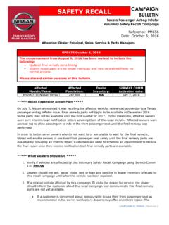
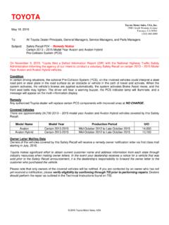
9 Fail - Engine oil not at correct IIIPAGE 3 OF 55 SAFETY RECALL 13S12-S2 CPR 2014 FORD MOTOR COMPANYDEARBORN, MICHIGAN 481214/2014 FIGURE A11235 CEVAP LINE QUICK CONNECTCOUPLINGCLAMPAIR INTAKE TUBETURBOCHARGERINLET PIPEAll VehiclesNOTICE: When working with liquid or vapor tube connectors, make sure to use compressed air to remove any foreign material from the connector retaining clip area before separating from the tube or damage to the tube or connector retaining clip can occur. Apply clean engine oil to the end of the tube before inserting the tube into the connector. NOTICE: Whenever turbocharger air intake system components are removed, always cover open ports to protect from debris. It is important that no foreign material enter the system.
10 The turbocharger compressor vanes are susceptible to damage from even small particles. All components should be inspected and cleaned, if necessary, prior to installation or reassembly. 8. Disconnect the EVAP line quick connect coupling from the air intake tube center section. Set the clip aside for re-installation to prevent it from falling into the engine compartment. See Figure A1. 9. Loosen the clamp and disconnect the air intake tube from the turbocharger inlet pipe. See Figure IIIPAGE 4 OF 55 SAFETY RECALL 13S12-S2 CPR 2014 FORD MOTOR COMPANYDEARBORN, MICHIGAN 481214/201411. Remove the battery tray. For additional information, refer to WSM Section 414-01. The air cleaner assembly was removed : The air cleaner assembly is removed from the vehicle with the mass air fl ow sensor and air intake tube Remove the air cleaner assembly.