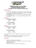
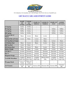
Transcription of *ALL NUMBERS SHOULD BE SET WITH DRIVER IN …
1 2017 TEAM GRT RACE CARS SETUP SHEET. *ALL NUMBERS SHOULD BE SET WITH. DRIVER IN CAR OR simulated . DRIVER weight !! RIDE HEIGHTS: G-60 TIRES. LF: 7 7/8 TO 8 FROM GROUND TO CENTER LINE OF LOWER A-FRAME BOLT. RF: 7 7/8 TO 8 FROM GROUND TO CENTER LINE OF LOWER A-FRAME BOLT. LR: WILL BE SET BY THE AMOUNT OF WEDGE. RR UNDER RAIL CARS: 2 3/4 TOP OF LOWER UNDERSLUNG TO BOTTOM OF. AXLE TUBE. RR OVER RAIL CARS: 12 3/4: FROM BOTTOM OF TOP FRAME TO TOP OF AXLE. TUBE. UMP/WISSOTA/AMRA/TSMA TIRES. LF: 8 TO 8 3/8 FROM GROUND TO CENTER LINE OF LOWER A-FRAME BOLT. RF: 8 TO 8 3/8 FROM GROUND TO CENTER LINE OF LOWER A-FRAME BOLT.
2 LR: WILL BE SET BY THE AMOUNT OF WEDGE. RR UNDER RAIL CARS: 2 TOP OF LOWER UNDERLSUNG TO BOTTOM OF. AXLE TUBE. RR OVER RAIL CARS: 12 : FROM BOTTOM OF TOP FRAME TO TOP OF AXLE. TUBE. SPRINGS: (STANDARD CONDITIONS). LF 500 RF 550. LR 200- 16 RR 175- 13 . SHOCKS: (STANDARD CONDITIONS) (SLICK CONDITIONS). LF 75-4 RF 74-10 LF RF 3-6. LR 7-2 RR 93-4 LR 7-2 RR 3. *Use Coil-Over Eliminator with spring behind the LR and shock in front in average to heavy tracks. *Use the coil-over spring & shock behind and no front shock when track is slick. *LR Max chain drop 18 bottom frame to top of the tube.
3 *RR Chain start at 14 and pull down as track starts to slicken off. PULL BAR: *Rear end mounting location is top front hole. *Pull bar 23 5/8 center to center @ 20 degree for short tight corners & 18 degree for sweeping longer corners. *Pinion angle 7 degree. *A 90/10 shock SHOULD be used with all pull bar applications. *TP Designed pull bar with 2 yellows, 1 red and pre-load * SHOULD check biscuits every 3-4 nights for height changes and for durometer change *Replace every 6-7 nights *Grease biscuits regularly- inside of canister outside of biscuits!!!! Grease everything, it will help the biscuits last longer and also improve the consistency of the pull bar PANHARD INFO: -Panhard bar is 19 center to center for Quickchange.
4 -Panhard frame mount is 3rd notch up -Wehrs J-Bar Mount 6 5/8 to bottom of the bracket & 7 3/8 to the center of bolt. -On 9 Ford panhard bar SHOULD be center of pinion. -Need 6 of split between mounting points REAREND INFO: *Rearend location is 15 from the inside edge of 2x2 to center of pinion at ride heights. *Rearend width is 60 centered LR BRAKE FLOATER: The more upward angle helps the car turn, freeing the car up on entry. The less upward angle tightens the car up on entry. *16 17 Center to Center 4-BAR LENGTHS: 16 On Top 13 On Bottom *Lead the RR back to on sweeping tracks.
5 *Lead the RR forward on track corners stop & go. **2014 and previous year model cars the 4-bar lengths may need to be 16 AND 13 . Check your engine set back measurement. This needs to be 72 from the front of the mid-plate to the center of the rear end. 4-BAR LOCATION: LR TOP 2nd HOLE UP. LR BOTTOM 2nd HOLE UP. RR TOP MIDDLE HOLE. RR BOTTOM 4TH HOLE UP. *All standard bar locations are notched on the frame. *Adjust lower left bar up to help car turn. *Adjust lower right bar down to tighten entry and up to free entry. **2017 Cars with the bolt in 4-link Brackets**.
6 -Left Side Spacers: Brake Floater . 1 3838S (3/4 x spaver for 5/8 heim). 1 3838BF (2017 Mod Brake Floater Heim Spacer). Left Top Rod . 1 shock bushing 1 shock bushing 1 3838OS (Oversize x Bushing for 5/8 Heim). 1 3838SL (3/4 x x 1 3/8 Long Spacer for Heim). Left Bottom Rod **Same as Left Tie Rod above. SPACER ORIENTATION: LS 4-Link: OS SL Center of Car RS 4-Link: Center of Car S SL. Spacer Part #: 3838S Spacer Part #: 3838SL. CASTER/CAMBER: RF CASTER 3 DEGREE TO 4 DEGREE POSITIVE. LF CASTER DEGREE TO 2 DEGREE POSITIVE. RF CAMBER - 5 DEGREE NEGATIVE. LF CAMBER - 4 DEGREE POSITIVE.
7 *Add more camber to higher banked tracks. *Toe out 3/8 to . BITE & %'S: LR BITE 50 LBS for traction 80 lbs for slick LEFT SIDE % % With 15 gallons of fuel REAR % 57 % For stop and go % For momentum *Use less rear on sweeping momentum tracks. *Use more rear on stop & go tight corners WHEEL OFFSET: *Use 2 offset wheels on LF, RF, LR and 3 on RR. * Or 3 offset all the way around with a 1 spacer on the LF,RF, and LR. RECOMMENDED TIRE AIR PRESSURE: LF: 10 #. RF: 12 #. LR: 8 #. RR: 12 #. TORQUE ARM INFO: -Torque Arm Cars use 73-6 shock and 250# spring. -32 center line of axle tube to center line of shock, for most tracks.
8 -Torque Arms require 6th rebound chain rubber kit for braking. -The rebound kit can also be used with pull bar to tighten car on corner entry. UPPER A-FRAME INFO: -A-Frames SHOULD be positioned in the top set of holes. -LF- 6 tube and clevis in the front, 7 tube in the back. -RF- 5 tube and clevis in the front, 6 tube in the back. -A-frames could be moved down to the lower set of holes on a small, high banked slick track to allow for more RF Camber gain. ENGINE PLATE INFO: -Engine plate SHOULD be mounted all the way to the left. - Located in the 2ND hole from the bottom * 1 inch spacer needs to go underneath the front engine mount.
9 BIRD CAGE MEASUREMENTS: 2017 Cars with the bolt in shock mounts: LR: Middle Hole is standard RR: Second Hole is from the outside is standard -7 from the edge of the rotor to the center of the shock mount. -Position the shock mount toward the center section. -Offset the rotors toward the center section while the rotors are positioned flat against the hub. -Be sure to have a separation from the center of the axle tube to the center of the 4-link rod heim. This applies to the top and bottom as well as the left and right of the car. *These measurements are based off the GRT/BSB and GRT/TWM birdcages.
10 *Wehrs Double Shear w/ 1 Rotors *7 3/8 edge of rotor to center of the shock mount *Shock Drop 7 LR and 6 on RR. *Shock Mounts mounted toward the center section *Wide spacer is toward the center *Narrow Spacer toward the wheel


