Transcription of allied tg bbox 0908 - Allied Commercial
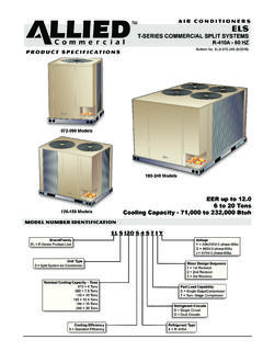
1 E N G I N E E R I N G D A T ATGROOFTOP UNITS60 HZP A C K A G E D G A S / E L E C T R I CBulletin No. TGA090 102 120 150 (08/09) to TonsNet Cooling Capacity 90,000 to 138,000 BtuhGas Input Heat Capacity 84,500 to 240,000 BtuhASHRAE NUMBER IDENTIFICATION TGAY1090HS2 BMajor Design SequenceA = 1st GenerationB = 2nd GenerationC = 3rd GenerationE = 4th GenerationBrand/FamilyT = Product LineUnit TypeG = Packaged Gas Heat w/ Electric CoolingNominal Cooling Capacity Tons090 = Tons102 = Tons120 = 10 Tons150 = TonsCooling EfficiencyS = Standard EfficiencyH = High EfficiencyMinor Design Sequence1 = 1st Revision2 = 2nd Revision3 = 3rd RevisionVoltageY = 208/230V-3 phase-60hzG = 460V-3 phase-60hzJ = 575V-3 phase-60hzHeating TypeS = Standard Gas Heat, 2 StageM = Medium Gas Heat, 2 StageH = High Gas Heat.
2 2 StageRefrigerant Type2 = R 22 Blower TypeB = Belt DrivePackaged Gas / Electric to tons / Page 2 TABLE OF CONTENTSB lower PerformancePage 16 18.. Cooling RatingsPages 12 15.. DimensionsPages 22 27.. Electrical DataPages 18 20.. Features and BenefitsPages 2 4.. High Altitude InformationPage 11.. Installation ClearancesPage 20.. Model Number IdentificationPage 1.. Optional AccessoriesPages 5 8.. SpecificationsPages 9 10.. Sound DataPage 15.. WeightsPage 21.. FEATURES AND BENEFITS APPROVALSETL and CSA listed. Componentsbonded for grounding to meet safetystandards for servicing required by UL,CSA and National and CanadianElectrical Codes. Gas efficiency ratingsverified by CSA. Cooling performancecertified in accordance with the ULEcertification program, which is based onARI Standard 340/360 STAR certified units aredesigned to use less energy, help savemoney on utility bills, and help protectthe 9001 Registered ManufacturingQuality ten years on aluminized steelheat five years on one year all other SYSTEMA luminized steel inshot burners, directspark ignition, electronic flame sensor,combustion air inducer, redundantautomatic dual stage gas valve withmanual ExchangerTubular construction, aluminized steel.
3 Life cycle Steel Heat Exchanger isrequired if mixed air temperature is lessthan 45 & Limit ControlsFactory installed with fixed limit controls protect SwitchesFlame roll out switches, flame sensorsand combustion air inducer provingswitches protect system operation. Allsafety switches are monitored by theignition control IgnitionSolid state electronic spark igniterprovides positive direct ignition ofburners on each operating cycle. Thesystem permits main gas valve to stayopen only when the burners are provento be lit. Should a loss of flame occur, thegas valve closes, shutting off the gas tothe burners. Ignition module has LED toindicate status and aid circuit on moduleautomatically resets ignition controlsafter one hour of continuous thermostatdemand after unit lockout, eliminatingnuisance service calls.
4 Ignition control isfactory installed in the controls SELECTIONSGas Input Order one (seeSpecification table for availablesizes):84,500/130,000 Btuh Standard HeatGas ,000/180,000 Btuh Medium HeatGas Input156,000/240,000 Btuh High Heat InstalledStainless Steel Heat ExchangerRequired if mixed air temperature isbelow 45 Heat SizeExtends heat input beyond Weather KitElectric heater automatically controlsminimum temperature in gas burnercompartment when temperature isbelow 40 F CSA certified to allowoperation of unit down to 60 InstalledCombustion Air Intake ExtensionsRecommended for use with existing flueextension kits in areas where high snowdrifts can block intake KitsConversion kit to field change over unitsfrom Natural Gas to Vent Extension KitExhausts flue gases vertically Mullion Gas Piping KitThe gas piping kit is used to make gaspiping connections from the
5 Unit mullionto the gas Base Gas Piping KitThe gas piping kit is used to make gaspiping connections through the unitbase up to the For gas piping from the unitbase to the gas valve, both kits arerequired and must be Gas / Electric to tons / Page 3 FEATURES AND BENEFITSBCDEFGHJIKLMNCOOLING SYSTEMD esigned to maximize sensible andlatent cooling performance at designconditions. Two efficiency levels provideflexibility. System can operate from 30 Fto 125 F without any additional mounted on rubbergrommets for quiet compressors on all models forhigh performance, reliability and Expansion ValvesAssures optimal performancethroughout the application element capacity filter/driers protect thesystem from dirt and the evaporator coil fromdamaging ice build up due to conditionssuch as low/no air flow, or low/norefrigerant ConstructionCopper tube construction, enhancedrippled edge aluminum fins, flaredshoulder tubing connections, silversoldered construction for improved heattransfer.
6 Factory leak CoilFace split with separate circuits. Eachcircuit has its separate expansion valve,compressor and refrigerant aluminum fins and coppertube coils with cross row circuitingoptimizes both sensible and latentcooling CoilFormed type on all edged, enhanced aluminum finand copper tube constructionmaximizes heat transfer Drain PanPainted, galvanized pan with connection extends outside Coil Fan MotorsThermal overload protected, totallyenclosed, permanently lubricated ballbearings, shaft up, independent Coil FanPVC coated fan guard SELECTIONSC ooling CapacitySpecify the nominal cooling capacity ofthe EfficiencySpecify either standard or InstalledCondensate Drain TrapAvailable in copper or Crankcase HeatersProtects against refrigerant migrationthat can occur during low Pressure SwitchesProtects the compressor from overloadconditions such as dirty condensercoils, blocked refrigerant flow, or loss ofoutdoor fan operation.
7 Manual Ambient KitCycles the outdoor fan while allowingcompressor operation in the coolingcycle. This intermittent fan operationallows the system to operate withouticing the evaporator coil and losingcapacity. Designed for use in ambienttemperatures no lower than 0 air fan provides a wide range ofair flow capability. Special order highand low static motor and drive optionsare available offering an even widerrange of Air MotorOverload protected with permanentlylubricated ball bearings ensures durableoperation. Belt drive motors that meetEPACT efficiency requirementsmaximize air performance and saveenergy. Special order high and low staticmotors provide a higher level of airperformance for Air BlowerA double inlet wheel with forward curveblades provide maximum airperformance and quiet balanced with permanentlylubricated ball bearings assure long,reliable operation.
8 Adjustable pulleysallow air to be precisely tuned to theneeds of the SELECTIONSS upply Air BlowerSpecify Blower motor and drive kit (SeeBlower Data Table for specifications).OPTIONS/ACCESSORIESF actory InstalledHigh and Low Static Supply FanExtends air flow external static Gas / Electric to tons / Page 4 FEATURES AND BENEFITS ELECTRICALREQUIRED SELECTIONSV oltage ChoiceSpecify 208/230V, 460V or 575V3 phase 60hz when ordering base InstalledCircuit Breakers up to 175 AmpHACR circuit breaker without powerdistribution lugs. Accessible fromoutside of unit, spring loadedweatherproof cover furnished. Mainpower to the unit is field connected to thecircuit breaker which allows all power tobe shutoff for service.
9 Circuit breaker issized to the unit maximum overcurrentprotection (MOCP) Switch up to 250 AmpAccessible from outside of unit, springloaded weatherproof cover power to the unit is field connectedto the disconnect which allows all powerto be shut off for Service Outlets (2)115v ground fault circuit interrupter(GFCI) type, field ControllerMicroprocessor based control boardprovides flexible control of coolingfunctions. All control voltage is providedvia a 24V (secondary) transformer withbuilt in circuit breaker in functions include:Blower On/Off Delay Time delaybetween blower on and off cyclesprovides a more even supply airtemperature during in Control Parameters Savesinstallation time as no programming Compressor Run Time Ensures proper oil return to Setback Mode Saves energyby closing outdoor air dampers andoperating supply fan on thermostatdemand Staging Capable of up to 2heat / 2 cool staging with a third partyDDC control system or Bounce Delay Protectscompressor from short cycling when amechanical thermostat is InstalledBlower Proving SwitchUses a static pressure sensor tomonitors blower operation and shutsdown unit if blower Filter
10 SwitchSenses static pressure increaseindicating dirty filter DetectorPhotoelectric type, installed in supply airsection or return air section or bothsectionsCABINETC onstructionHeavy gauge steel panels and fullperimeter heavy gauge galvanizedsteel base rail provides structuralintegrity for transportation, handling,and installation. Base rails have riggingholes. Three sides of the base rail havefork slots. Raised edges around ductand power entry openings in the bottomof the unit provide additional protectionagainst water entering the Flow ChoiceUnits are available in down flow (vertical)or horizontal air flow configuration withoptional field installed HorizontalConversion FlangesHorizontal supply duct flange isstandard on all EntryElectrical and gas lines can be broughtthrough the unit base or throughhorizontal access knock PanelsConstructed of heavy gauge,galvanized steel with a two layerenamel paint finish.