Transcription of ALLOWABLE STRESS DESIGN OF CONCRETE …
1 An information series from the national authority on CONCRETE masonry technologyNCMA TEK 14-7C 1 ALLOWABLE STRESS DESIGN OF CONCRETE masonry BASED ON THE 2012 IBC & 2011 MSJCTEK 14-7 CStructural (2013)INTRODUCTION CONCRETE masonry elements can be designed by using one of several methods in accordance with the International Building Code (IBC, ref. 2) and, by reference, Building Code Require-ments for masonry Structures (MSJC Code, ref. 1): ALLOWABLE STRESS DESIGN , strength DESIGN , direct DESIGN , empirical DESIGN , or prestressed masonry . This TEK provides a basic overview of DESIGN criteria and requirements for CONCRETE masonry as-semblies designed using ALLOWABLE STRESS DESIGN provisions.
2 For masonry DESIGN in accordance with the strength DESIGN , prestressed or empirical provisions, the reader is referred to TEK 14-4B, Strength DESIGN Provisions for CONCRETE masonry (ref. 5), TEK 14-20A, Post-Tensioned CONCRETE masonry Wall DESIGN (ref. 10), and TEK 14-8B, Empirical DESIGN of CONCRETE masonry Walls (ref. 4), respectively. The content presented in this edition of TEK 14-7C is based on the requirements of the 2012 International Building Code (ref. 2a), which in turn references the 2011 edition of the MSJC Code (ref. 1a). For designs based on the 2006 or 2009 IBC (refs. 2b, 2c), which reference the 2005 and 2008 MSJC (refs. 1b, 1c), respectively, the reader is referred to TEK 14-7B (ref.)
3 11). Significant changes were made to the ALLOWABLE STRESS DESIGN (ASD) method between the 2009 and 2012 editions of the IBC. In previous codes, the IBC included alternative load combinations for ASD, and the MSJC ASD criteria allowed a one-third increase in ALLOWABLE stresses for load combinations that include wind or seismic. The one-third STRESS increase is not included in the 2011 MSJC. In addition, previous code versions allowed the use of strength-level load combinations in ASD to compensate for the lack of service-level load combinations in previously referenced versions of ASCE 7, Minimum DESIGN Loads for Buildings and Other Structures (ref. 3). Currently, however, ASCE 7-10 includes both service level and strength level load combinations, so this "pseudo-strength" procedure is no longer included in the current ASD TEK:12-4D, 14-1B, 14-4B, 14-5A, 14-7B, 14-8B, 14-19A, 14-20 AKeywords: ALLOWABLE loads, ALLOWABLE STRESS , ALLOWABLE STRESS DESIGN , axial strength, building code provisions, flexural strength, reinforced CONCRETE mason-ry, shear strength, structural DESIGN , unreinforced CONCRETE masonry This TEK provides a general review of the pertinent al-lowable STRESS DESIGN criteria contained within the 2011 MSJC.
4 ALLOWABLE STRESS DESIGN is based on the following DESIGN principles and assumptions: Within the range of ALLOWABLE stresses, masonry elements satisfy applicable conditions of equilibrium and compat-ibility of strains. Stresses remain in the elastic range. Plane sections before bending remain plane after bending. Therefore, strains in masonry and reinforcement are directly proportional to the distances from the neutral axis. STRESS is linearly proportional to strain within the ALLOWABLE STRESS range. For unreinforced masonry , the resistance of the reinforce-ment, if present, is neglected. For reinforced masonry DESIGN , all tensile stresses are re-sisted by the steel reinforcement.
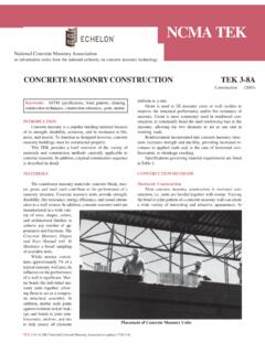
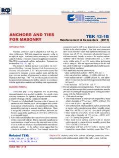
5 masonry in tension does not contribute to axial or flexural strength. The units, mortar, grout, and reinforcement, if present, act compositely to resist applied loads. Based on these assumptions, the internal distribution of stresses and resulting equilibrium is illustrated in Figure 1 for unreinforced masonry and Figure 2 for reinforced masonry . Using ALLOWABLE STRESS DESIGN , the calculated DESIGN stresses on a masonry member (indicated by lowercase f) are compared to code-prescribed maximum ALLOWABLE stresses (indicated by a capital F). The DESIGN is acceptable when the calculated applied stresses are less than or equal to the ALLOWABLE stresses (f < F). DESIGN LOADS Utilizing ASD, masonry elements are sized and pro-portioned such that the anticipated service level loads can be safely and economically resisted using the specified material strengths.
6 The specified strength of masonry and 2 NCMA TEK 14-7 Creinforcement are in turn reduced by appropriate safety fac-tors. Minimum DESIGN loads for ALLOWABLE STRESS DESIGN are included in ASCE 7-10, Minimum DESIGN Loads for Buildings and Other Structures, or obtained from the IBC. UNREINFORCED masonry For unreinforced masonry , the masonry assembly (units, mortar, and grout if used) is designed to carry all applied stresses (see Figure 1). The additional capacity from the inclusion of reinforcing steel, such as reinforcement added for the control of shrinkage cracking or prescriptively required by the code, is neglected. Because the masonry is intended to resist both tension and compression stresses resulting from applied loads, the masonry must be designed to remain Out-of-Plane Flexure ALLOWABLE flexural tension values as prescribed in the 2011 MSJC Code vary with the direction of span, mortar type, bond pattern, and percentage of grouting as shown in Table 1.
7 For assemblies spanning horizontally between supports, the code conservatively assumes that masonry constructed in a bond pattern other than running bond cannot reliably transfer flexural tension stresses across the head joints. As such, the ALLOWABLE flexural tension values parallel to the bed joints (perpendicular to the head joints) in these cases are assumed to be zero. In cases where a continuous section of grout crosses the head joint, such as would occur with the use of open-ended units or bond beam units with recessed webs, tension resisted only by the minimum cross-sectional area of the grout may be considered. Because the compressive strength of masonry is much larger than its corresponding tensile strength, the capacity of unreinforced masonry subjected to net flexural stresses is al-most always controlled by the flexural tension values of Table 1.
8 For masonry elements subjected to a bending moment, M, and a compressive axial force, P, the resulting flexural bending STRESS is determined using Equation 1. fMtIPAbnn= 2 Eqn. 1 TEK 14-1B, Section Properties of CONCRETE masonry Walls (ref. 6) provides typical values for the net moment of inertia, In, and cross-sectional area, An, for various wall sections. If the value of the bending STRESS , fb, given by Equation 1 is positive, the masonry section is controlled by tension and the limiting values of Table 1 must be satisfied. Conversely, if fb as given by Equation 1 is negative, the masonry section is in compres-sion and the compressive STRESS limitation of Equation 2 must be met. fb < Fb = 1/3 f'm Eqn.
9 2 Unreinforced Axial Compression and Flexure While unreinforced masonry can resist flexural tension stresses due to applied loads, unreinforced masonry is not permitted to be subjected to net axial tension, such as that due to wind uplift on a roof connected to a masonry wall or the overturning effects of lateral loads. While compressive stresses from dead loads can be used to offset tensile stresses, reinforcement must be incorporated to resist the resulting tensile forces when the element is subject to a net axial tension. When masonry elements are subjected to compressive axial loads only, the calculated compressive STRESS due to ap-Figure 1 Unreinforced masonry STRESS DistributionFigure 2 Reinforced masonry STRESS Distribution 2A: Neutral axis within the 2B: Neutral axis within compression face shell the core areaWall widthbfWall widthMasonry coverBar diameterTC13kdkdjddMasonry coverBar diameterWall width13kdkdTCjddfbbf3B3 ANCMA TEK 14-7C 3plied load, fa, must not exceed the ALLOWABLE compressive STRESS , Fa, as given by Equations 3 or 4, as elements having h/r < 99: fFfhraam = 1411402' Eqn.
10 3 For elements having h/r > 99: fFfrhaam = 14702' Eqn. 4 A further check for stability against an eccentrically applied axial load is included with Equation 5, whereby the axial com-pressive load, P, is limited to one-fourth the buckling load, Pe. With Equation 5, the actual eccentricity of the applied load, e, is used to determine Pe. Moments on the assembly due to loads other than the eccentric load are not considered in Equation = 141410577223 . Eqn. 5 When unreinforced masonry elements are subjected to a combination of axial load and flexural bending, a unity equation is used to proportion the available ALLOWABLE stresses to the applied loads per Equation 6. This check ensures that the critical sections remain uncracked under DESIGN loads.