Transcription of Alphasense Application Note AAN 105-03 …
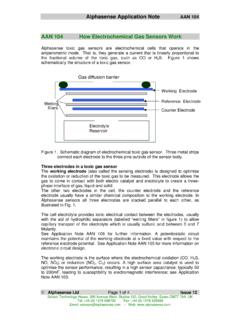
1 Alphasense Application Note AAN 105-03 Alphasense Limited Page 1 of 5 March 2009 Sensor Technology House, 300 Avenue West, Skyline 120, Great Notley, Essex CM77 7 AATel: +44 (0) 1376 556700 Fax: +44 (0) 1376 335899 email: Web: 105-03 DESIGNING A POTENTIOSTATIC CIRCUITI ntroductionIn a three-electrode sensor, each electrode has a specific use: The working electrode responds to the target gas, either oxidising or reducing the gas,creating a current flow that is proportional to the gas concentration. This current must besupplied to the sensor through the counter electrode. The reference electrode is used by the potentiostatic circuit to maintain a fixed potential at theworking electrode. The working electrode potential must be maintained at the same potentialas the reference electrode potential for unbiased sensors, or with an offset for sensors thatrequire biasing.
2 The counter electrode completes the circuit with the working electrode, reducing somechemical species (normally oxygen) if the working electrode is oxidising, or oxidising if theworking electrode is reducing the target gas. The potential of the counter electrode is allowedto float, sometimes changing as the gas concentration increases. The potential on the counterelectrode is not important, so long as the potentiostat circuit can provide sufficient voltage andcurrent to maintain the working electrode at the same potential as the reference 1 is a circuit diagram of a zero bias potentiostat circuit. Refer to this during the 1 Preferred potentiostat circuit for zero bias toxic gas sensors. ICs require +/-, not singleended power to 100R10k10k10k1nF10nFOutputsignalC1C2R1R2 R loadR5R4R3C31 MDSG--++Q1+V Alphasense Application Note AAN 105-03 Alphasense Limited Page 2 of 5 March 2009 Sensor Technology House, 300 Avenue West, Skyline 120, Great Notley, Essex CM77 7 AATel: +44 (0) 1376 556700 Fax: +44 (0) 1376 335899 email: Web: typical potentiostat circuit consists of three parts:1 Control circuit with bias voltage, if required2 Current measuring circuit3 Shorting FET to connect the working electrode to the reference electrode when power is offControl CircuitThe control op amp (IC2 in figure 1) provides the current to the counter electrode to balance thecurrent required by the working inverting input into IC2 is connected to the reference electrode and must not draw anysignificant current from the reference electrode.
3 An op amp with an input bias current of less than5nA is switching on the circuit, the depletion mode JFET (Q1 in Fig 1) goes to a high impedancestate and IC2 provides the current to maintain the working electrode at the same potential as thereference electrode. Any offset due to the input offset voltage in IC2 will therefore cause a suddenshift in potential at switch-on. Toxic gas sensors have a large capacitance, so significant currentscan flow for small potential shifts, so ensure that your op amp has a low offset voltage, certainlyless than 1 mV and preferably less than 100 V; also check the op amp offset voltage at themaximum usage , for an oxidisable gas (such as CO) with a platinum reference electrode, the counterelectrode will be -300 to -400mV from the ground potential. However, if hydrogen ions rather thanoxygen molecules are reduced, then the potential could be as large as Also, reducinggases (such as NO2 or Chlorine) force the counter electrode to oxidise water, evolving oxygen; inthis case the potential relative to the reference electrode is between +600 and +800 mV,depending on the type of reference electrode.
4 Therefore, you must allow IC2 enough voltageswing to drive the counter electrode to the required potential and with sufficient current demandedby the sensor. If the circuit is unable to do this, then extreme non-linearities will occur at higherconcentrations. It is best to allow swing on IC2 (plus any imposed bias voltage). This meansthat for a CO or H2S sensor the counter electrode wants to be typically -350 mV below the groundpoint, so IC2 needs a negative supply. If you are using a single ended low voltage power supply,pay particular attention to the available output swing on the op amp at the required 1 below shows the maximum generated steady state current for each type of sensor. At fullscale no sensor generates more than 210 A, but allow at least 500 A for a general purposecircuit, although this can be decreased for specific, well tested sensor/ circuit when switching the circuit ON in the presence of an electroactive gas or when a newsensor is first connected, the sensor may give a surge current of several mA that may cause IC1 toclamp, depending on the current drive capacity of IC1; it is unlikely that IC1 can maintain the virtualearth on its inverting input with a high feedback resistor during such a high current connect the sensor before powering the stability and noise reduction in the control circuit relies on R1, R2, C1 and C2; C2 may notbe necessary for certain op amps.
5 If eliminating C2, then C1 may be increased- between 10 and100 nF. Suggested op amps are OP90 (single op amp) and OP 296 (dual op amp). Alphasense Application Note AAN 105-03 Alphasense Limited Page 3 of 5 March 2009 Sensor Technology House, 300 Avenue West, Skyline 120, Great Notley, Essex CM77 7 AATel: +44 (0) 1376 556700 Fax: +44 (0) 1376 335899 email: Web: voltageNormally, Alphasense toxic gas sensors are operated in the zero bias mode; however, certainsensors, such as NO sensors, require a bias voltage: typically 150 or 300mV for an NO , sensor cross-sensitivity to certain gases can be enhanced by adding a bias ! performance can also be degraded if you bias incorrectly! Remember thatbiasing a normally unbiased sensor may damage the sensor and certainly voids the sensorwarranty. Consult Alphasense for further you wish to inject a bias voltage then also ensure that your bias voltage is stable: changes ofeven a few mV can affect sensitivity to gases and rapid changes in the bias voltage by only a mVwill generate transient effects for up to hours on the sensor output.
6 A simple method of biasing thesensor is shown in figure 2 below. The 10K load resistor to ground can be removed to reduce thecurrent on 2. Applying a bias voltage to the control op should be maintained when the instrument is switched off - this is normally accomplishedby using a button cell battery that remains on at all times. In this case, the input offset of IC2 is notcritical, but its drift with temperature etc. must be kept Measuring CircuitThe measuring circuit is a single stage op amp (IC1) in a transimpedance configuration; the sensorcurrent is reflected across R4, generating an output voltage relative to the virtual earth. C3 reduceshigh frequency noise. It is sometimes desirable to use two opamp stages to give the requiredoutput; the first stage should use a low value for R4 to allow the circuit to oppose the sensorcurrent in transient conditions, followed by a second voltage gain stage to give the required input offset voltage of IC1 will add to the sensor bias voltage (as the working electrode will beoffset from 0V) so the input offset should be kept low.
7 Remember that the generated current canbe either positive or negative: sensors that oxidise at the working electrode ( CO) generate acurrent into IC2, while reducing working electrodes ( Cl2 or NO2) sink a current. So for thesecond case, ensure that IC2 has adequate current sinking +- Alphasense Application Note AAN 105-03 Alphasense Limited Page 4 of 5 March 2009 Sensor Technology House, 300 Avenue West, Skyline 120, Great Notley, Essex CM77 7 AATel: +44 (0) 1376 556700 Fax: +44 (0) 1376 335899 email: Web: measuring circuit uses a combination of the (load resistor (Rload) plus internal sensorresistance) and the (internal sensor capacitance) to establish an RC circuit; the selection of Rload isa compromise between fastest response time (low resistance Rload) and best noise (high resistanceRload): this RC circuit affects both the rms noise and the response time: the response timeincreases linearly with increasing Rload resistance, while noise decreases rapidly with increasingRload resistance.
8 If you need highest resolution, then forfeit fast response time. Likewise, if fastresponse time is critical, then reduce the resolution of your display or sample the signal faster andaverage over several readings in software to eliminate jitter. Due to the low impedance nature ofthe circuit, it is better to use an opamp with low noise current (usually at the expense of noisevoltage) to get the best overall noise sensor current flows through Rload, there will be a small change to the sensor bias has the effect of increasing the sensor settling time as the sensor will require a short time tore-stabilise when gas is applied, but this transient will normally not be seen except at high gasconcentrations and high Rload to Table 1 below to calculate the required gain for your measuring circuit. If your detector/instrument does not use the full scale of the sensor, then simply multiply the Sensitivity by yourRange to determine the maximum current from the sensor.
9 Since the sensitivity is the typicalvalue, allow 20% more than the typical full scale output into your A/D (ppm)Sensitivity(nA/ppm)(typical)Full Scaleoutput( A)Full Scaleoutput(V)Calibrationpoint(ppm)CO-BF , CO-B1, CO-BX1, 400CO-AF1, , 10, 2,000CO-DF1, 501, 20H2S-BH502, , 400H2S-AE2, , , , 1. List of output parameters and calibration point for Alphasense toxic gas sensors. Alphasense Application Note AAN 105-03 Alphasense Limited Page 5 of 5 March 2009 Sensor Technology House, 300 Avenue West, Skyline 120, Great Notley, Essex CM77 7 AATel: +44 (0) 1376 556700 Fax: +44 (0) 1376 335899 email: Web: FETIt is normal practice to add a shorting FET for unbiased sensors so that the reference and workingelectrodes are shorted together (with a residual resistance of a few tens of ohms) when power isremoved from the circuit. This ensures that the working electrode is maintained at the samepotential as the reference electrode when the circuit is switched off.
10 The shorting FET is normallyopen circuit as long as power is applied. This zero bias state ensures that when you switch thecircuit back on, the sensor is ready immediately. If you do not use a shorting FET and leave thesensor open circuit when the circuit is off, the toxic gas sensor will take a few hours to stabilisewhen next switched you are supplying a bias voltage through IC2, then when you switch off the circuit, the sensor willbe zero biased and hence when you reapply a bias voltage it will take a significant time (up toseveral hours) for the sensor to re-establish equilibrium. It is recommended that, for biasedcircuits, the bias voltage be maintained on at all times and the shorting FET not used. This willnot affect the operating life of the JFET (Q1) should be a p-type FET. Recommended FET types include surface mount or TO-92 packages as per Table 2 CodeTypeSiliconixSST177 Surface MountSiliconixJ175TO-92 SiliconixJ176TO-92 SiliconixJ177TO-92 FairchildJ175TO-92 Table 2.