Transcription of ALUMINUM ELECTROLYTIC CAPACITORS ES Bi …
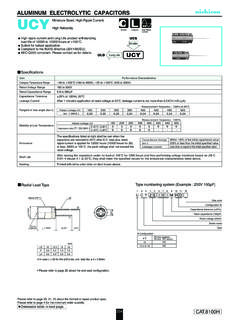
1 ALUMINUM ELECTROLYTIC refer to page 20, 21, 22 about the formed or taped product refer to page 4 for the minimum order tolerance ( 20%) Rated capacitance (47 F) Rated voltage (10V) Series nameType 16 HML+ vent15 MIN4 MINS leeve ( ) d D+ DP ( ) ( D < 10) ( D 10) (mm)P , For Audio EquipmentBi-polarized nichicon MUSE acoustic for audio signal to the RoHS directive (2011/65/EU).Radial Lead TypeType numbering system (Example : 10V 47 F) SpecificationsCategory Temperature RangeRated Voltage RangeRated Capacitance RangeCapacitance ToleranceLeakage CurrentTangent of loss angle (tan )Stability at Low TemperatureEnduranceShelf LifeMarkingPerformance CharacteristicsItem 40 to +85 to to 1000 F 20% at 120Hz, 20 CAfter 1 minute's application of rated voltage at 20 C, leakage current is not more than or 3 ( A), whichever is with black color letter on clear green frequency : 120Hz at 20 CMeasurement frequency.
2 120 HzCapacitance changeLeakage currentThe specifications listed at right shall be met when the CAPACITORS are restored to 20 C after the rated voltage is applied for 1000 hours at 85 C with the polarity inverted every 250 storing the CAPACITORS under no load at 85 C for 1000 hours and then performing voltage treatment based on JIS C 5101-4 clause at 20 C, they shall meet the specified values for the endurance characteristics listed Within 20% of the initial capacitance value150% or less than the initial specified valueLess than or equal to the initial specified valueRated voltage (V)tan (MAX.) 25 C / Z+20 CZ 40 C / Z+20 CRated voltage (V)Impedance ratioZT / Z20 (MAX.) 1 10 22 33 47 100 220 330 470 1000 R47 010 2R2 3R3 4R7 100 220 330 470 101 221 331 471 102 5 11 11 8 10 10 16 10 20 5 11 11 11 10 10 16 10 20 20 16 251A10 5 11 11 11 8 10 10 20 20 25 16 251C16 5 11 5 11 11 8 10 10 16 25 25 16 25 16 5 11 11 8 10 10 10 20 25 16 25 16 251V35 5 11 5 11 5 11 5 11 11 8 10 10 16 10 20 25 16 25 16 D L (mm)VCodeCap.
3 ( F)Bi-polarized Please refer to page 20 about the end seal configuration.