Transcription of ALUMINUM ELECTROLYTIC CAPACITORS UCM Chip Type ...
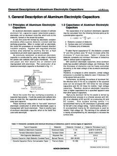
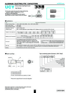
1 ALUMINUM ELECTROLYTIC CAPACITORS . UCM Chip Type, Low Impedance Chip type, low impedance temperature range up to +105 C. UCL. Applicable to automatic mounting machine fed with carrier tape. Smaller Compliant to the RoHS directive (2011/65/EU). Higher capacitance AEC-Q200 compliant. Please contact us for details. UCM. Smaller Higher capacitance Specifications Specifications UCV. Item Item PerformancePerformance Characteristics Characteristics Category CategoryTemperature TemperatureRange Range 55. 55to +105C. to +105 C. Rated Rated Voltage Voltage Range Range to 50V. to 50V. Rated Capacitance Range 10 to 2200 F. Rated Capacitance Range 10 to 2200 F. Capacitance Tolerance 20% at 120Hz, 20C.
2 Capacitance Tolerance 20% at 120Hz, 20 C of rated voltage, leakage current is not more than Leakage Current After 2 minute's application Leakage Current After 2 minutes' application of rated voltage at 20 C, leakage current is not more than CV ( A). frequency : 120Hz, Measurement Rated voltage (V) 10 16 25 35 50. Tangent of loss angle (tan ) Measurement frequency : 120Hz at 20 C. Tangent of loss angle (tan ). Rated tan voltage (V) (MAX.) 16 25 35 50 Temperature : 20C. tan (MAX.) Rated voltage (V). 10 25 3516 50 Measurement frequency : 120Hz 50 2 Measurement frequency : 120Hz Stability at Low Temperature Rated voltage Z 25C /(V). Z+20C 2 210 25. 2 352 216. Impedance ratio Z 25 C / Z+20 C 3 2 2 23 23.
3 Stability at Low Temperature ZT /Impedance ratio Z 40C / Z+20C 32 3 32. Z20 (MAX.) Z 40 C / Z+20 C 4 3 3 33 33. ZT / Z20 (MAX.) Z 55C / Z+20C 43 3 43. Z 55 C / Z+20 C 4 4 3 3 4 3. Capacitance Change Within 30% of the initial capacitance value Endurance tan . Capacitance change 200% or less than the initial specified value The specifications listed at right shall be met Within 30% of the initial capacitance value Leakage current Less than or equal to the initial specified value Endurance when the CAPACITORS are restored to 20 C after the tan 200% or less than the initial specified value After storing rated the CAPACITORS voltage is appliedunder no load for 2000 at 105C. hours for 1000 hours at 105 C.
4 And then Leakage Less than performing voltage current or equal to treatment the initial based on JISspecified valueclause C 5101-4. Shelf Life at 20C, they shall meet the specified values for the endurance characteristics listed above. After storing the CAPACITORS under no load at 105 C for 1000 hoursCapacitance and then performing voltage treatment based on JIS C 5101-4. Change Within 10% of the initial capacitance value Shelf Life Resistance to clause at 20 C, they shall meet the specified values for the endurance characteristics listed above. soldering heat tan Less than or equal to the initial specified value The CAPACITORS are kept on a hot plate for 30 seconds, which is LeakageCapacitance change current Less thanWithin or equal 10%toofthe theinitial initial specified capacitance value value Resistance to soldering maintained at 250 C.
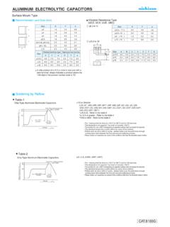
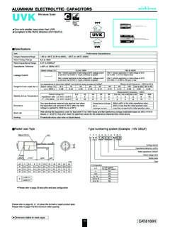
5 The CAPACITORS shall meet the characteristic tan Less than or equal to the initial specified value Marking heat Black print on the case requirements listedtop. at right when they are removed from the plate Leakage current Less than or equal to the initial specified value and restored to 20 C. Marking Black print on the case top. 1 2 3 4 5 6 7 8 9 10 11 12 13 14. Positive U CM 1 C 1 0 1 M C L 1 GS. Plastic platform Voltage( C : 16V ). Chip Type Series C Type numbering system (Example : 16V 100 F). Taping code ( 4 to ) Size code A 100C. D Configuration B CM. a2. E. A Capacitance tolerance (20%) Configuration Lot No. Capacitance Rated capacitance (100F) D Code L Negative Rated voltage (16V) 4 to CL.
6 H. 8 10 NL. Series name Positive Plastic platform . Type Voltage( E : 25V ) C Trade mark Series (mm). A D L. ( 8, 10 ) 4 5 8 10 10 10. D 470E. B A CM. E. a2. A B Lot No. Capacitance C L Negative E Pressure relief vent H. L 10 10. H to to to to to to Voltage V 10 16 25 35 50. Code j A C E V H. Voltage V 10 16 25 35 50. Code j A C E V H. Dimension table in next page. 138 ALUMINUM ELECTROLYTIC CAPACITORS . UCM. Dimensions V 10 16 25 35 50. Code 0J 1A 1C 1E 1V 1H. 4 85. 10 100. 5 165. 22 220 4 160 4 160 5 165. 33 330 4 160 5 240. 47 470 4 160 5 240 5 240 195. 68 680 4 160 5 240 5 240 300. 100 101 4 160 5 240 300 300 350. 150 151 5 240 300 600 600. 220 221 5 240 300 300 600 8 10 670. 330 331 300 600 600 8 10 850 10 10 900.
7 470 471 600 600 8 10 850. 560 561 10 10 1190. 680 681 600 8 10 850. 820 821 10 10 1190. 1000 102 8 10 850 10 10 1190. 1500 152 8 10 850 10 10 1190. Impedance Rated ripple 2200 222 10 10 1190 . MAX. Impedance ( ) at 20 100kHz, Rated ripple current(mArms) at 105 100kHz In this case, 6 will be put at 12th digit of type numbering system. Frequency coefficient of rated ripple current Frequency coefficient of rated ripple current Frequency Frequency 50Hz 120Hz 300Hz 1kHz 10kHz or more 50 Hz 120 Hz 300 Hz 1 kHz 10 kHz or more Coefficient Coefficient Taping specifications are given in page 23. Recommended land size, soldering by refrow are given in page 18, 19. Please refer to page 3 for the minimum order quantity.
8 139