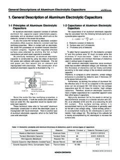
Transcription of ALUMINUM ELECTROLYTIC TECHNICAL NOTE 1 General …
1 101 NOTED esign, Specifications are subject to change without factory for TECHNICAL specifications before purchase and/or ELECTROLYTICCAPACITORSTECHNICAL ( )1 General Description of ALUMINUM Elec-trolytic Capacitors 1-1 The Principle of CapacitorThe principle of capacitor can be presented by theprinciple drawing as in a voltage is applied between the metal elec-trodes placed opposite on both surfaces of a dielec-tric, electric charge can be stored proportional to VQ : Quantity of electricity (C)V : Voltage (V)C : Capacitance (F) C. called the capacitance of capacitor, is expressed bythe following expression with the electrode area S[m2],the electrode spacing t [m] and the dielectric constantof dielectric :C[F] = 0 0: Dielectric constant in vacuum ( = 12F/m ) The dielectric constant of an ALUMINUM oxide film is7 to 8.
2 Larger capacitances can be obtained by en-larging the electrode area S or reducing t. Table 1-1 shows the dielectric constants of typical diel-ectrics used in the capacitor. In many cases, capacitornames are determined by the dielectric material used,for example, ALUMINUM ELECTROLYTIC capacitor, tantalumcapacitor, etc. Although the ALUMINUM ELECTROLYTIC capacitor is small,it has a large capacitance. It is because the electrodearea is roughened by electrochemical etching, en-larging the electrode area and also because the die-lectric is very schematic cross section of the ALUMINUM electrol-ytic capacitor is as in Equivalent Circuit of the CapacitorThe electrical equivalent circuit of the ALUMINUM elec-trolytic capacitor is as presented in Fig.
3 : Resistance of terminal and electrodeR2 : Resistances of anodic oxide film and electrolyteR3 : Insulation resistance because of defective anodicoxide filmD1 : Oxide semiconductor of anode foilC1 :Capacity of anode foilC2 : Capacity of cathode foil L : Inductance caused by terminals, electrodes, etc. 2 About the Life of an ALUMINUM ElectrolyticCapacitor2-1 Estimation of life with minimal ripple current(negligible).Generally, the life of an ALUMINUM ELECTROLYTIC capacitoris closely related with its ambient temperature and thelife will be approximately the same as the one obtainedby Arrhenius effects to the life by derating of the applied voltageetc. are neglected because they are small comparedto that by the tAnodic oxide filmAnode foilElectrolyte(True cathode) air oxide filmCathode foil(Virtually, electrode forcathode extraction)Separator sheetimpregnated with electrolyteR1R2C2LC1D1R3L = L0x (1)Where L : Life at temperature TL0.
4 Life at temperature T0T0 T 10)) ALUMINUM oxide filmMylarMica7 to to8 Porcelain (ceramic)PolystyreneTantalum oxide film10 to to 20 Table 1 DielectricDielectric ConstantDielectricDielectric Constant102 NOTED esign, Specifications are subject to change without factory for TECHNICAL specifications before purchase and/or ELECTROLYTICCAPACITORSTECHNICAL ( )2-2 Estimation of life considering the ripple ripple current affects the life of a capacitorbecause the internal loss (ESR) generates heat. Thegenerated heat will be:P = (2)Where l : Ripple current (Arms)R : ESR ( )With increase in the temperature of the capacitor: T =..(3)Where T : Temperature increase in the capacitorcore(deg.
5 I : Ripple current (Arms) R : ESR ( ) A : Surface area of the capacitor (cm2) H : Radiation coefficient (Approx. ~ x10 3W/cm2x C)The above equation (3) shows that the temperature ofa capacitor increases in proportion to the square ofthe applied ripple current and ESR, and in inverseproportion to the surface area. Therefore, the amountof the ripple current determines the heat generation,which affects the life. The value of T varies de-pending on the capacitor types and operating condi-tions. The usage is generally desirable if T remainsless than 5 C. The measuring point for temperatureincrease due to ripplecurrent is shown below;Test results: (1) The life equation considering the ambient temper-ature and the ripple current will be:L = Ld x 2 x K.
6 (4)Where Ld: Life at DC operation (h)K: Ripple acceleration factor(K=2, if with in allowable ripple current)(K=4, if exceeding allowable ripple current)T0: Maximum guaranteed temperature ( C)T: Operating temperature ( C) T: Temperature increase at capacitor core(deg.)(2) The life equation based on the life with the ratedripple current applied under the maximum guaranteedtemperature will be a conversion of the above equation(4), as below:L = Lr x 2 x K ..(5)Where Lr: Life at the maximum guaranteed tempera-ture with the rated ripple current (h) T0: Temperature increase at capacitor core,at the maximum guaranteed temperature(deg.)(3) The life equation considering the ambient temper-ature and the ripple current will be a conversion ofthe above equation (5), as below:L = Lr x 2 x K.
7 (6)Where l0: Rated ripple current at the maximum guar-anteed temperature (Arms)I : Applied ripple current (Arms)Since it is actually difficult to measure the temperatureincrease at the capacitor core , the following table isprovided for conversion from the surface temperatureincrease to the core temperature life expectancy formula shall in principle beapplied to the temperature range between the ambienttemper-ature of +40 C and maximum allowableworking temperature. The expected life time shall beabout fifteen years at maximum as a guide in termsof deterioration of the yearAmbient temperature of capacitor ( C)Operating24hh(103h)8h/daycondition2050 100131175three yearsthree yearsnineyearsfifteenyearsfifteenyearste nyearsfiveyears(Table 2-1 Life Expectancy Chart)85 C:1000hour guaranteed112233445566778899101012121111 85 C:2000hour guaranteed105 C:1000hour guaranteed105 C:2000hour guaranteed105 C:3000hour guaranteed105 C:5000hour guaranteed105 C:20000hour guaranteed125 C:1000hour guaranteed125 C:1250hour guaranteed125 C:2000hour guaranteed125 C:3000hour guaranteed125 C.
8 5000hour guaranteedMeasuring pointI2 R A HT0 T 10)) T 10))T0 T 10)) T0 T 10))T0 T 10))I1 I0 T0x 10)2 )Table 2-1 Case diameterCore / Surface~ ~ , Specifications are subject to change without factory for TECHNICAL specifications before purchase and/or ELECTROLYTICCAPACITORSTECHNICAL ( )2-2 Practical Examples of Life ExpectancyAs practical examples of life expectancy, we introduce250V 560 F in the LAG Series considering the effectof high-frequency component. Figures 2-1 to 2-3 showthe simulated ripple current waveforms when the high-frequency component for switching is superimposed onthe commercial frequency of the above may be obtained as the effectiveripple current value.
9 Assuming that the ripple currentwaveform of the low-frequency component is generallyapproximated to the full-wave rectification waveform asshown in , we obtain the effective ripple currentvalue ILas follows:Since the ripple current waveform of the high-frequencycomponent is approximated to the rectangular asshown in , the effective current value of high-frequency component IHis given byThe reason why the ripple current affects the life isdue to the heat generated by the ESR (R) of is, T by heat generation can be expressed by T I2 R from Expression (2).Therefore, when ripple currents with different frequen-cies are handled, each current value must first besquared and then summed.
10 That is:Now, we proceed to specific examples assuming thatthe effective ripple current values of low-and high-frequencies have been obtained by the above A (Test piece and basic data)To verify the effect of the high-frequency component,the expected life will be calculated for each of threehigh-frequency ripple current BFor Data B, the currents are converted to 120 Hz by thefrequency conversion factor for the cases of ignoranceof the high-frequency component, and each high-frequency component = = ( )2+( ) ( )2+( ) ( )2+( ) here is about the frequency conversionfactor. As described above, the heat generation (ortemperature rise = T) affecting the life is proportionalto the ESR of capacitor.
