Transcription of Amphenol
1 AmphenolAmphenol Neptune SeriesConnectors for Power ApplicationsSL-NEPH eavy Duty - Environmental Power ConnectorsContentsNeptune Series Overview 2 Environmental Highlights 3 Captive Contact Inserts 4 Connector Assemblies 4 Electrical Ratings 5 Termination Data 6 Wire Limitation Guide 6 Coupling Nut Torque 6 Code Logic 7NP/NPE - Straight Plug 8NR - Square Flange Receptacle 9 NRM - Square Flange Receptacle with Mechanical Clamp Nut 10 NRIM - In-Line Receptacle 11 NRBA - Receptacle Mounted to Junction Box with Angle Adapter 12 NRBA - Receptacle Mounted to Junction Box with Straight Adapter 13 Neptune 30 Amp Plug 14 30 Amp Receptacle 15 60 Amp Plug 16 60 Amp Receptacle 17 100 Amp Plug 18 100 Amp Receptacle 19 150 Amp Plug 20 150 Amp Receptacle 21 200 Amp Plug 22 200 Amp Receptacle 23 Neptune Connector Assembly and Termination Instructions 24 Sales Offi ces and Distributors Listing 25 Catalog information for reference only.
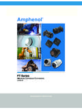
2 For more assistance, contact your local Amphenol fi eld sales offi ce or: Amphenol Industrial Operations4300 N. Sam Houston Parkway WestSuite 400 Houston, TX 77086 Phone: 1-281-866-0588 Fax: 1-281-866-0597 Technical email: catalog and most all Amphenol catalogs are available for viewing, printing and downloading on Oil & Gas TechnologiesAmphenolNEPTUNE SeriesNeptune Series connectors are heavy duty environmentally sealed plugs and receptacles and have been successfully used in all types of Industrial applications. These compact environmental connectors have provided outstanding performance in complex ground support cable networks, process control systems and instrumentation family of connectors has made a major contribution to the successful interconnection of peak power generating systems as well as offshore petroleum production for power distribution and data margins of safety and reliability have been designed into the Neptune connectors to maintain capability levels which make them ideally suited for the broad spectrum of demands placed on them by specifi c materials and design features incorporated in Neptune connectors were originally selected to satisfy the stringent requirements of the Aerospace industry for heavy-duty connectors .
3 These connectors combine electrical and mechanical capabilities that equal or exceed the perform ance parameters established by the Military Specifi cation MIL-5015. UL & CSA listed to UL1682/CSA requirements ENVIRONMENTAL RESISTANCE Design and materials withstand the most challenging operating conditions. Series has an IP 68-8 rating. PRESSURE TERMINALS EASILY ACCESSIBLE WIRE TERMINALS Conductors are readily terminated to contacts. Cable housings are slipped over conductors or leads after terminating. Cumbersome handling and seating of inserts with conductors attached is eliminated. LARGE WIRING SPACE Ample wiring space is provided in cable housings and conduit fi tting bodies. Hub of body mounts in any of four positions. REVERSIBLE INSERTS A full range of contact inserts and application adapters are available. All are interchangeable and reversible to suit reverse service requirements.
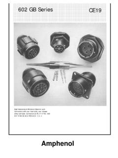
4 DOUBLE-LEAD THREAD COUPLING Modifi ed Acme Thread does not clog under adverse conditions of ice, snow, sand or mud and provides the quick coupling feature. HARD ANODIC COATING All machined, aluminum parts fi nished with a hard, scratch-resistant coating per MIL-A-8625, Type III. Dielectric strength 1800 volts. Heat resistance of 750 F. HIGH TENSILE STRENGTH ALUMINUM Bar Stock Components precision machined. Points of impact designed for extra strength. RoHS COMPLIANT PRODUCT AVAILABLE Consult Amphenol Oil & Gas parallel thread removedto show actual thread angle. Standard double-lead Acme. Two parallel threads. Why the Double-Lead Acme Thread?The double-lead Acme thread is a moderate torque quick-coupling thread which permits complete coupling in approximately one turn of the coupling nut. In addition, there are actually two parallel threads having starting points 180 degrees apart. All of this ensures that plugs and receptacles are being mated or unmated thread contour makes it & Gas TechnologiesNEPTUNE AmphenolEnvironmental Highlights MIL-5015 REQUIREMENTS CLASSES A, B, E NEPTUNEPROPERTY J & R CONNECTORSTEMPERATURE -67 F to 225 F Temperature Classes A, B, E, (-55 C to 107 C) J and R can withstand 257 F continuously.
5 For short duration high-temperature life, consult No requirement 300 PSI external (coupled connectors ) 200 PSI internal (with pin and socket inserts)AIR LEAKAGE 1 cubic inch/ Exceeds Classes E hour maximum and R specifi cationsHUMIDITY AND 1 1/2 times Exceeds ClassesMOISTURE voltage rating after E and 14 days. MIL-5015 Exposure to Meets MIL-STD-202B, 95% relative Method 106A humidity at 160 48 Hours Salt spray: 300 daysRESISTANCE Method 1001 No exposure of base metal.
6 MIL-STD-1344 No exposure of base No requirement Oil, most acidsRESISTANCE and No requirement Meets MIL-STD-202B,RESISTANCE Method 110, Condition BSHOCK 50 G minimum Exceeds 60 G sRESISTANCE Certain inserts available to 200 Method 2005 Exceeds Method II & Method II MIL-STD-167-1 (Ships). MIL-STD-1344 TEST PROBE Contact size Exceeds MIL-5015 ABUSE No. 16 and No. 18 on all contacts No. 18 through 4 Oil & Gas TechnologiesAmphenolNEPTUNE PressurePadDouble Lead Acme ThreadShell SealAdapter SealAdapter WasherPressurePadCable AdapterCoupling NutPlug ShellRigid Front InsulatorResilient Contact Seal LaminantRigid Rear InsulatorReceptacleShellSelf-sealing Construction: all captive contact inserts are capable of being terminated after assembly in the basic barrel and are completely self-sealing when pressurized by any selected adapter.
7 Water, gas, vapor, moisture or dust positively cannot pass in either direction through or around the sandwich construction of inserts consists of a resilient silicone laminate between two rigid plastic insulators. The resilient laminate seals absorbs shock and vibration and allows the contacts to align them selves freely. The rigid faced plastic insulators impart just the right amount of restraint to retain the contacts in combined sandwich provides all the advantages of resilient mounting plus all the advantages of rigid mounting, with none of the shortcomings of either. Under pressure, between a shoulder and a thrust washer, the silicone reacts as a fl uid and being non-compressible, fl ows against all surfaces to affect a reli able seal around the periphery of the insert and around all contacts where they penetrate the insulation. Contact cavities are clearly numbered on the front and rear insert face to facilitate identifi cation during assem bly, inspection and maintenance.
8 Socket insulator contact cavities are of a bellmouth guided entry design. These chamfered lead-ins insure easy and positive mating of male AssembliesTypical Plug ComponentsTypical Receptacle ComponentsCaptive Contact InsertsOil & Gas TechnologiesNEPTUNE AmphenolNEPTUNE 5 Three Classifi cations of Ampere RatingsMS Ampere Ratings: (MIL-C-39029)Based on the combination of the following:The amount of current which an individual pin and socket contact may carry is a function of contact material and design effi ciency of the pin and socket system as well as the ability of the primary conductor insulation to resist temperature rises due to inherent copper losses and bundling current carrying capacity of the connector is a function of the insert temperature which is rated at 225 F (107 C) for continuous operation. The total operating temperature is the summation of the ambient temperature plus the temperature rise resulting from the thermal losses of each specifi cations may be used as a general reference on the subject inasmuch as pertinent cable derating data is Non-Circuit-Breaking or Disconnect Ampere RatingsThe non-interrupting current ratings, shown in the table, are based on the temperature of the contacts being within the range specifi ed by Underwriter s Laboratories, Inc.
9 When wire sizes are selected in accordance with the National Electrical multiple conductors are used, the load factor and temperature rise based on ambient and total insert temperature must be taken into Voltage RatingsThe voltage to which contact inserts are lim ited is a function of the dielectric separation between adjacent contacts and between contacts and voltage rating is designated by a service voltage rating letter which is shown in the service voltage rating table with each contact confi guration : The circuit breaking and non-circuit breaking ratings are based on test results of contacts and connectors . Consult the when selecting wire/cable for specifi c applications. Under certain conditions, a wire size may be rated higher or lower than the table indicates for a given contact size. Measurements made at extreme ends of mated contacts with probe touching contact and wire (MIL-5015 specifi cations).
10 ** Based on temperature rise (National Electrical Code Requirement).** Based on Arcing Control (National Electrical Code Requirement). MIlitary Ratings Ratings MIL-5015 Non- Circuit Over Specifi cations Circuit Breaking Surface Thru-Air Non-Circuit Distance Spacing Breaking Inches Inches Service Nominal Nominal Voltage Volts Volts RMS RMS RMS RMS Instrument 250 200