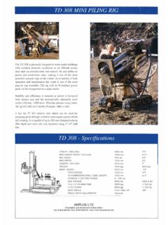
Transcription of AMPLUS LTD METHOD STATEMENT - BOREHOLES - ROTARY METHOD OF ...
1 AMPLUS LTD METHOD STATEMENT - BOREHOLES - ROTARY METHOD OF EXCAVATION - MACHINE - FRASTE PL RIG PROJECT NO: 1 GENERAL All work will be carried out by experienced drillers trained to guidelines of the British Drilling Association and in accordance with BS5939: 1999. All operatives will have received training in Health and Safety, site activity/awareness and their individual tasks. Before the commencement of any site works, the drilling operatives will have received information on the site and the BOREHOLES , dynamic sampling and trial pits. This will include a Job Information Sheet for the site that will have been completed by the Project Engineer.
2 The appropriate sheet for this site includes information on: 1. Access routes to the site that have been agreed with the Project Manager/engineer. 2. Confirmation that underground service location plans have been made available by the Client/Engineer and that services are not located below borehole and trial pit positions. (This is to be confirmed on the Permit to Dig Form). 3. The site designation in accordance with Appendix V of the Institution of Civil Engineers' Guidelines for the safe investigation by drilling of landfills and contaminated land and thereby the Personal Protective Equipment (PPE) that should be worn by site staff.
3 4. The specification for the site investigation, including borehole and trial pit depths, testing type and frequency, sampling frequency and reinstatement requirements. 5. The number of piezometer installations and their configuration. 6. The requirement or otherwise for inspection pits to check for services. 7. Restrictions on working hours. 8. Height limitations. 2 FIELDWORK ACTIVITIES The following section describes the activities associated with the investigation of a site. Mobilisation and set-up ROTARY Drilling Sub-sampling or coring and reinstatement of holes Date of Issue: 25/01/08 Page 1 of 4 AMPLUS Ltd Issue 1 - Revision 0 Mobilisation and set-up 1.
4 All operations will be undertaken by the Drilling Foreman and Assistant Driller, who are responsible for their own Health and Safety and that of any other people affected by site works. 2. All equipment and material required for site work will be loaded into a Landrover or similar vehicle to be transported to site. 3. Either a Landrover or similar will be used to tow the trailer carrying the Fraste PL Rig to site or a Hiab lorry will lift and carry the rig to site. 4. Heras fencing will be erected around the working area to provide a barrier between the works and the public. Signs will be erected to indicate to members of the public that they must not enter the site without prior authorisation.
5 5. Before entering the site, all personnel will wear PPE appropriate to the site. This site can be categorised as 'yellow' under the Guidelines for the safe drilling of landfills and contaminated land. 6. At the locations marked out by the Client or the Engineer, a CAT scanner will be used to verify that no electric cables run below trial pit or borehole positions. If the CAT scanner indicates the presence of any electric cables, the Drilling Foreman will notify the Engineer immediately. With the agreement of the Engineer, the investigation hole will then be displaced to the nearest position that there are no cables according to the CAT scanner. 7. After the CAT survey, any paving slabs will be lifted.
6 Where possible, slabs will be preserved for reuse during reinstatement. 8. Given that there is uncertainty surrounding the accuracy or otherwise of the service drawings that exist for the site, an inspection pit will be excavated to for the borehole . Inspection pits will be excavated using hand tools such as picks and shovels. 9. Any other hand-dug trial pits will be excavated in the same manner as inspection pits. Samples will be taken at the rate specified on the Job Information Sheet. 10. If material that appears to be contaminated is encountered during pitting, the Drilling Foreman shall suspend work. Work shall only recommence when all workers are attired in the appropriate PPE for the contamination.
7 Samples of any potentially contaminated material shall be taken for geochemical testing. 11. On completion of the inspection pit, the drilling rig is to be placed over the borehole position. 12. The rig will be erected in a safe manner in accordance with the operating manual, on a firm and level working surface, using timber baulking and taking precautions to prevent toppling and 'runaway'. Particular attention will be given to overhead cables, structures and parked cars. Date of Issue: 25/01/08 Page 2 of 4 AMPLUS Ltd Issue 1 - Revision 0 ROTARY Drilling 1. The rig will be operated in accordance with the manufacturer's specification and BDA Code of Safe Drilling Practice.
8 2. Working areas will be kept free as practicable from borehole arisings and equipment not actually in use. Particular attention to be paid to 'trip' hazards. 3. Dry drilling and ROTARY core drilling methods will be used to form open holes and obtain cores in superficial deposits and rock. 4. Dry Drilling The drilling rod is placed in the ROTARY drilling head of the rig. The chuck is then sufficiently tightened to grip rod, onto which the drilling barrel is then screwed by hand. The drilling barrel is then lowered to the bottom of the hole and rotation of drilling had commenced. The hole is drilled to the depth of an in-situ test or refusal.
9 Rotation is stopped and the depth noted. The drilling head is used to withdraw the drill rods, which are broken from each other and the core barrel using hydraulic clamps. The core barrel is lifted using the winch rope. Rods are lifted and then broken using the clamps. The condition of the winch rope must be checked daily by the driller and replaced with an approved replacement at the first sign of wear or damage. Finally, the barrel is broken down using bacho spanners and samples are extruded using the hydraulic ram. 5. ROTARY Coring If dry drilling is resulting in limited sample returns ROTARY coring shall commence. The ROTARY coring METHOD requires water.
10 Water is supplied to the pump using a hose from a 1000 gallon water tank. The water tank will be filled by a bowser and inert polymer added to aid drilling to the manufacturer's recommended dosage. The same METHOD of sample recovery as described for dry drilling is used. 6. Casing off hole If cave-in of the borehole occurs, casing will be flushed into the hole. Casing is flushed into the holes using the same METHOD as described in ROTARY Coring above. 7. At the depths specified by the Engineer, or at every change in strata, an SPT test will be carried out. The drilling rods will be extracted from the hole in the same manner as for dry and ROTARY drilling.


