Transcription of AN-772, A Design and Manufacturing Guide for the Lead ...
1 AN-772 ApplicAtioN Noteone technology Way . Box 9106 Norwood, MA 02062-9106 tel: 781/329-4700 Fax: 781/461-3113 of ConTenTsIntroduction ..1 Description ..1board Design Considerations ..2assembly Considerations ..5 Rework ..7 Thermal Performance ..9electrical Characteristics ..10solder Joint Reliability ..12 References ..14a Design and Manufacturing Guide for the lead frame Chip scale Package (lfCsP)by Gary GriffinInTRoDUCTIonThis application note provides Design and manu-facturing guidance in the use of the lead frame chip scale package (LFCSP). The LFCSP is compliant with JEDEC MO220 and MO229 outlines. DesCRIPTIonThe LFCSP is a near chip scale package (CSP), a plastic encapsulated wire bond package with a copper lead frame substrate in a leadless package input/output pads are located on the outside edges of the package.
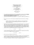
2 Electrical contact to the printed circuit board (PCB) is made by soldering the perimeter pads and exposed paddle on the bottom surface of the package to the PCB. Heat is efficiently conducted from the package by soldering the exposed thermal paddle (see Figure 1) to the PCB. Stable electrical ground connections are provided through down bonds and through conductive die attach material. Wire bonding is provided using gold wires (see Figure 2). Perimeter and thermal pad finish is plated as Sn / Pb solder or 100% Sn. Packaging is in tape and reel or pADGolDWiReMolDiNGcoMpoUNDeXpoSeDtHeRMAl pADDlepiN 1peRiMeteRi/o pADS(leADS)Figure 1. Isometric Cut Away View of the LFCSPREV. 0 2 AN-772 The LFCSP is ideally suited to hand-held mobile appli-cation or any application where weight and size is an issue.
3 It allows higher density PCB application than the corresponding leaded package FRAMeDie AttAcHpADDleDieepoXYSolDeRplAtiNGNote:tH e pAcKAGe i/o pADS ARe cAlleD leADS to AVoiD coNFUSioN WitH tHe lAND 2. Cross Section of the LFCSPThe detailed package outline of the LFCSP is shown in Figure 3. piN MiNeXpoSeDpAD(BottoM VieW)AbFigure 3. LFCSP Outline Drawing (JEDEC MO-220)ADI packages are punched or sawed from a molded strip during final assembly. Half-etching of the lead frame provides mold compound locking features for the perimeter pads and die thermal paddle (see Figure 4). This package is currently characterized as moisture sensitivity (MSL) level 3 (see JEDEC J-STD-20 for MSL levels).DieleADFRAM eetcHeDlocKFeAtUReFigure 4.
4 Lead Frame Locking Featuresbenefits over standard Plastic PackagesLFCSP technology of fer s a number of signif icant benefits over standard plastic packages : Reduction in board mounting space as die size is closer to the package size. Superior electrical characteristics are obtained due to elimination of leads reducing electrical path lengths from the die to PCB. Lower thermal resistance because the exposed paddle is soldered to the PCB. The lead frame process utilizes existing proven lead frame package technology. Standard SMT assembly equipment can be used; no underfill is required. High assembly yields can be realized from the self-aligning characteristic of the low mass package during solder Design ConsIDeRaTIonsFor optimum performance, special consideration should be given in designing the motherboard and mounting the package.
5 For enhanced thermal, electrical, and board level performance, the exposed paddle on the bottom of the package is soldered to the corresponding thermal land paddle on the PCB. Thermal vias are designed into the PCB land paddle area to further improve heat number of factors may have a significant effect on mounting the LFCSP package on the board and the qualit y of solder joints, including board material, board thickness, PCB perimeter pad Design , thermal paddle and via Design , stencil Design , solder paste, and solder Material Standard epoxy glass substrates (FR-4) are compatible with LFCSP assembly. Use of substrate with lower coef ficient of thermal expansion (CTE) can improve reliabilit y.
6 The CTE of a PCB can also be af fected by factors such as number of metal layers, laminate materials, trace density, operating environment, site population density, and mounting on the reverse side of the 0 3 AN-772land Pattern Design GuideThe PCB land pattern for the LFCSP is designed based on guidelines developed by the board assembler, or by following an industry standard such as IPC-SM-782. However, because of exposed thermal paddle and the package perimeter pads on the bottom side of the package, constraints should be added to the IPC meth-odology. The land patterns outlined in ADI application notes are for guideline purposes only, and factor in perimeter pads and package land PatternThe PCB land pattern for the LFCSP is defined in Figure 5.
7 The tolerance analysis requires the consideration of: Component tolerances PCB tolerances Accuracy of the equipment used for placing the componentFor component tolerances, the profile tolerances usually given in the package outline drawing are converted into maximum material condition (MMC) and least material condition (LMC) based tolerances. The board tolerance defines the difference between the MMC and LMC of each pattern dimension. Here PCB tolerance is assumed to be mm; equipment placement tolerance is also assumed to be 'cplADMAXD2'ZDMAXGDMiNFigure 5. Land Pattern or PCB Footprint JSSec. A-AJtAAJHeXpoSeDcoppeR(cu)Figure I. Toe, Heel, and side fillets for the lfCsPJT min Minimum Toe Fillet mmJH min Minimum Heel Fillet mmJS min Minimum Side Fillet mmThe minimum values for solder joint fillets, defined in Table I, are used to calculate the land pat tern dimensions.
8 The values are selected recognizing that both sides and one end of the leads are embedded in the mold compound, and solder fillets cannot be formed on these sides. The fourth side has the full lead thickness of copper (Cu) exposed on the side of the package. By Design , this lead thickness is exposed copper since the leads are cut after plating. The cutting action on the leads is from the bottom to the top of the package, which results in the bottom section of the exposed copper get ting covered with solder. It is generally accepted that the toe fillets are formed depending on the type of solder paste used and length of exposure of the package to environmental conditions, but this cannot be guaranteed.
9 IPC / EIA J-STD-001 does not require a toe fillet on the lead edge with exposed copper for bottom-only values of toe, heel, and side fillets are con-sidered for the formation of reliable solder joints. The toe fillet will improve the solder joint reliability, and provision should be made for its formation. land Pattern Design CalculationsTo find the guideline dimensions for the layout of the land t t p : / / w w w . a n a l o g . c o m / A n a l o g _ R o o t / P a c k a g e s /Packages_Home/Land pattern dimensions are determined initially using the following:ZDMAX = DMIN + 2JT + TTNote: DMIN is the package external outline minimum value. Table II. XMaX Values Depend on PitchPitch mm mm mmXMAX mm mm mm mmAs shown in Table II, XMAX is set smaller than bMAX, the max package lead width for mm pitch to avoid solder III.
10 Approximate Values for TT and TsTT mm mmAs shown in Table III, TT and TS are the rms values of toe and side tolerances, which account for component, board, and placement tolerances. The calculations for these values are defined in more detail in 0 4 AN-772 The calculation for GDMIN does not account for the leads on adjacent sides of the package. To avoid any solder bridging between the two perpendicular leads on each corner, a minimum clearance, CLL, is needed. This clear-ance is assumed as mm and the value of GDMIN is determined using the following constraint:GDMIN ADMAX + 2 CLLwhere:ADMAX = [(lead pitch) 3 (no. of leads on side 1)] + pad widthThe pad length is determined as follows:Y = (ZDMAX GDMIN)/2To ensure a robust Design and to minimize any possibility of solder bridging during board assembly, a minimum metal-to-metal clearance of mm is required.