Transcription of An Analysis and Performance Evaluation of a Passive Filter ...
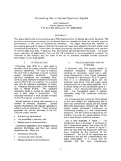
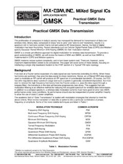
1 TL/W/12473An Analysis and Performance Evaluation of a Passive FilterDesign Technique for Charge Pump Phase-Locked LoopsAN-1001 National SemiconductorApplication Note 1001 William O. KeeseMay 1996An Analysis andPerformance Evaluationof a Passive FilterDesign Technique forCharge PumpPhase-Locked LoopsThe high Performance of today s digital phase-lock loopmakes it the preferred choice for generation of stable, lownoise, tunable local oscillators in wireless communicationsapplications. This paper investigates the design of passiveloop filters for Frequency Synthesizers utilizing a Phase-Frequency Detector and a current switch charge pump suchas National Semiconductor s PLLatinumTMSeries. Passivefilter design for a TYPE II third order phase-lock loop is dis-cussed in depth, with some discussion of higher order filtersincluded. Specific test results are presented for a GSM syn-thesizer design. Optimization of phase-lock loop perform-ance with respect to different parameters is basic phase-lock-loop configuration we will be consid-ering is shown inFigure 1.
2 The PLL consists of a high-stabil-ity crystal reference oscillator, a frequency synthesizer suchas the National Semiconductor LMX2315TM, a voltage con-trolled oscillator (VCO), and a Passive loop Filter . The fre-quency synthesizer includes a phase detector, currentmode charge pump, and programmable frequency Passive Filter is desirable for its simplicity, low cost, andlow phase most standard PLL s there are several design parameterswhich can be treated as constant values. This linear approx-imation provides a good estimation of loop values of the PLL Filter design constants depend onthe specific application. For example, Kwis determined bythe synthesizer charge pump output current magnitude. Thenotation and definitions for these values along with standardunits used throughout this paper are given in Table I I. PLL Filter Design ConstantsKvco - (MHz/Volt)Voltage Controlled Oscillator (VCO) Tuning Voltageconstant. The frequency vs voltage tuning (mA/2qrad)Phase detector/charge pump constant.
3 The ratio of thecurrent output to the input phase - (MHz)Radio Frequency output of the VCO at which the loopfilter is - (kHz)Frequency of the phase detector inputs. Usually equiva-lent to the RF channel divider ratio. Equal to 1 FIGURE 1. Basic Charge Pump Phase Locked LoopReprinted with permission from Argus a trademark of National Semiconductor National Semiconductor CorporationRRD-B30M56/Printed in U. S. basic knowledge of control loop theory is necessaryin order to understand PLL Filter dynamics. For a more thor-ough treatment consult references[1]through[6]. A linearmathematical model representing the phase of the PLL inthe locked state is presented inFigure 2. An additional inte-grator is needed in the transfer function for the forward gainand is usually lumped together with the VCO in the litera-ture, references[1-4]. Using the simplified diagram inFigure2, and feedback theory, one may obtain the equations forthe phase transfer functions presented in Table 2 FIGURE 2.
4 PLL Linear ModelTABLE II. PLL Phase Transfer FunctionsForward loop gaineG(s)eHo/HeeKwZ(s) Kvco/sReverse loop gaineH(s)eHi/Hoe1/NOpen loop gaineH(s) G(s)eHi/HeeKwZ(s)Kvco/NsClosed loop gaineHo/HreG(s)/[1aH(s) G(s)]The standard Passive loop Filter configuration for a type IIcurrent mode charge pump PLL is shown inFigure 3. Theloop Filter is a complex impedance in parallel with the inputcapacitance of the VCO, or in other words, a driving 3 FIGURE 3. 2nd Order Passive FilterThe phase detector s current source outputs pump chargeinto the loop Filter , which then converts the charge into theVCO s control voltage. The shunt capacitor C1 is recom-mended to avoid discrete voltage steps at the control portof the VCO due to the instantaneous changes in the chargepump current output. A low pass Filter section may be need-ed for some high Performance synthesizer applications thatrequire additional rejection of the reference sidebands,known as method of Filter design uses the open loop gain band-width and phase margin to determine the component val-ues.
5 Locating the point of minimum phase shift at the unitygain frequency of the open loop response as shown inFig-ure 4ensures loop stability. The phase relationship betweenthe pole and zero also allows easy determination of the loopfilter component values. The phase margin,wp, is definedas the difference between 180 and the phase of the openloop transfer function at the frequency,0p, correspondingto 0-dB gain. The phase margin is chosen between 30 and70 . When designing for a higher phase margin you trade offhigher stability for a slower loop response time and lessattenuation of Fref. A common rule of thumb is to begin yourdesign with a 45 phase 4 FIGURE 4. Open Loop Response Bode PlotThe impedance of the second order Filter inFigure 3isZ(s)es(C2#R2)a1s2(C1#C2#R2)asC1asC2(1 )Define the time constants which determine the pole andzero frequencies of the Filter transfer function by lettingT1eR2#C1#C2C1aC2(2a) T2eR2#C2(2b)Thus the 3rd order PLL Open Loop Gain in Table II can becalculated in terms of frequency,0, the Filter time constantsT1 and T2, and the design constants Kw, Kvco, and (s)#H(s) sej#0ebKpd#Kvco (1aj0#T2)02C1#N(1aj0#T1)#T1T2(3)From equation 3 we can see that the phase term will bedependent on the single pole and zero such that the phasemargin is determined in equation 4.
6 The available phasemargin therefore is proportional to the ratio of C1 and (0)etanb1(0#T2)btanb1(0#T1)a180 (4)By setting the derivative of the phase margin equal to zeroas shown in equation 5,dwd0eT21a(0#T2)2bT11a(0#T1)2e0(5)the frequency point corresponding to the phase inflectionpoint is found in terms of the Filter time constants T1 and relationship is given in equation #T1(6) insure loop stability, we want the phase margin to bemaximum when the magnitude of the open loop gain equals1. Equation 3 then givesC1eKpd#Kvco#T10p2#N#T2 (1aj0p#T2)(1aj0p#T1) (7)Therefore, if the loop bandwidth,0p, and the phase margin,wp, are specified, equations 1 through 7 allow us to calcu-late the two time constants, T1 and formulas for T1 and T2 are shown in equations 8 and (8)T2e10p2#T1(9)From the time constants, T1, T2, and the loop bandwidth,0p, the values for C1, R2, and C2 are obtained in equations10 to #Kpd#Kvco0p2#N01a(0p#T2)21a(0p#T1)2(10)C 2eC1##T2T1b1J(11)R2eT2C2(12)Current switching noise in the dividers and the charge pumpat the reference rate, Fref, may cause unwanted FM side-bands at the RF output.
7 In wireless communications, thephase detector comparison frequency is generally a multipleof the RF channel spacing. These spurious sidebands cancause noise in adjacent channels. Additional filtering of thereference spurs is often times necessary, depending onhow narrow your loop Filter is. This is usually the case intoday s TDMA digital cellular standards, such as GSM, PDC,PHS, or IS-54. The sub-millisecond lock times necessary forswitching between channel frequencies makes a relativelywide loop Filter mandatory. For these Performance criticalsynthesizer applications placing a series resistor and ashunt capacitor prior to the VCO provides a low pass polefor more attenuation of unwanted spurs. The use of a pas-sive loop Filter eliminates the noise contributions from an opamp in an active Filter . This is critical due to the strict error, and integrated phase noise requirements. Therecommended Filter configuration is shown inFigure added attenuation from the low pass Filter is:ATTENe20 log[(2qFref#R3#C3)2a1](13)Defining the additional Filter time constant asT3eR3#C3(14)Then in terms of the attenuation of the reference spurs add-ed by the low pass pole we haveT3e010(ATTN/20)b1(2q#Fref)2(15)TL/W/ 12473 5 FIGURE 5.
8 3rd Order Lowpass FilterThe additional pole must be lower than the reference fre-quency, in order to significantly attenuate the spurs, butmust be at least 5 times higher than the loop bandwidth, orthe loop will almost assuredly become unstable. In order tocompensate for the added low pass section, the Filter com-ponent values are recalculated using the new open loopunity gain frequency,0c, as in equation 17. The degradationof phase margin caused by the added low pass is then miti-gated by slightly increasing C1 and C2 while slightly de-creasing R2. Note that0cis slightlyk0p, therefore thefrequency jump lock time will increase. Although not exact,the linear assumptions used in this design technique pro-vide suprisingly good results for loop Filter bandwidths of upto(/5of the reference rate. The derivation of0cis includedin the [0c2#(T1aT3)](16)0cetanw#(T1aT3)[(T1aT3) 2aT1#T3]c(17) 01a(T1aT3)2aT1#T3[tanw#(T1aT3)]2b1(C1eT1 T2 Kpd#Kvco0c2#Nc(18) (1a0c2#T22)(1a0c2#T12)(1a0c2#T32)((/2 Similar to the 2nd Order Filter we haveC2eC1##T2T1b1J;(11)R2eT2C2(12)The only component values that need to be determinedcomprise the added low pass pole.))))
9 Since these values aresolely determined from equations 13 and 14, their valuesare somewhat arbitrary. It is not prudent, however to have acapacitor value for C3 which is equal to or greater than theother capacitors. As rule of thumb choose C3sC1/10,otherwise T3 will interact with the primary poles of the , choose R3 at least twice the value of R2. Whenselecting C3 you must also take into account the input ca-pacitance of the VCO tuning varactor diode which will add following example is a typical synthesizer developed forthe Global System Mobile (GSM) digital cellular standardusing the described Filter design technique. The RF channelspacing is 200 kHz, and a typical synthesizer frequencyrange is from 865 MHz 915 MHz. Since the addition of alow pass Filter will reduce the closed loop bandwidth slightly,select an initial design value which is slightly larger MHzFrefe200 kHzNeRFopt/Frefe45000pe2q*20 ATTENe20 (20/20)b1(2q#200e3) ( )[( ) # ]c 01a( ) # [( )]2b1( ( )2#( ) ( )#20ea6( )2#4500c [1a( )2#( )2][1a( )2#( )2ll1a( )2#( )2](( nF## nF; kX;if we choose R3e22 kX; pFConverting the calculated numbers to standard componentvalues gives the Filter shown in the test board schematic forthe synthesizer implementation,Figure results for the PLL loop Filter design using a NationalSemiconductor LMX2315 Frequency Synthesizer are shownin the following pages.)))
10 A 10 MHz crystal oscillator was usedas the reference oscillator input signal. The supply voltagewas 5V, and the entire current consumption, including theVCO, wask15 6 FIGURE 6. Test Fixture 7to9show HP8566 Spectrum Analyzer measure-ments of the RF output. The measured closed loop filterbandwidth is between 15 kHz and kHz. The referencespurious level iss70 dBc, due to the loop Filter attenuationand the low spurious noise level of the LMX2315. Thephase noise level at 1 kHz offset inFigure dBc/Hz. This correlates to a phase noise floor ofs150 relatively flat PLL closed loop characteristics gives ameasured RMS. phase error ofk2 , and is also an indicatorof good loop concern in any PLL loop Filter design is the time it takesto lock in to a new frequency when switching channels. TheHP53310A Modulation Domain Analyzer plots inFigures 10and11show the positive and negative switching waveformsfor a frequency jump of 865 MHz 915 MHz. The well bal-anced charge pump of the LMX2315 frequency synthesizercauses the waveforms to be nearly inverted replicas of eachother.