Transcription of An Analysis of Lift and Drag Forces of NACA Airfoils Using ...
1 International Journal of Application or Innovation in Engineering & Management (IJAIEM) Web Site: Email: Volume 4, Issue 4, April 2015 ISSN 2319 - 4847 Volume 4, Issue 4, April 2015 Page 198 ABSTRACT The aerodynamic Airfoils of wind turbine blades have crucial influence on aerodynamic efficiency of wind turbine. This involves the selection of a suitable Airfoil section for the proposed wind turbine blade. Lift and Drag Forces along with the angle of attack are the important parameters in a wind turbine system. These parameters decide the efficiency of the wind turbine. In this paper an attempt is made to study the Lift and Drag Forces in a wind turbine blade for NACA0012, NACA4412 & NACA6412 Airfoil profile is considered for Analysis .
2 Data for the Angle of Attack, Co efficient of Lift and Drag of NACA Airfoil taken from NACA Airfoil Tool. Lift and Drag Forces Analysis for different parameters is carried out Using PYTHON(x,y) programming. xlrd library used to read the Airfoil data from excel file. Keywords: Lift Forces , Drag Forces , NACA Airfoils , Python. One of the most important parameter of wind turbines is wing because wind hits to the wings and energy of wind is transformed into the mechanical energy by wings. In the literature, wings profiles are called as Airfoils . Airfoil profile is the important parameter for wing design because wing efficiency increases depending on Airfoil profile, so there are a lot of studies over the Airfoil profile as numerical and experimental in the literature [1]. Airfoil information is used explicitly in the optimization process.
3 Wind tunnel test data of several Airfoils which are publicly available are collected and stored as an Airfoil database. This database includes Lift, Drag and Angle of Attack data of many Airfoils developed for or used in wind turbine applications [1,2]. OA Angle of attack Cd Drag coefficient Cl Lift coefficient Fd Drag force Fl Lift force V Wind velocity Vrel Relative velocity tpr Tip Speed Ratio c Chord Length l Blade element length rho Air density An Analysis of Lift and Drag Forces of NACA Airfoils Using Python B Patel, Sandip T Patel2, Divyesh T Patel3, Maulik Bhensdadiya4 1M E scholar Government Engineering College, Valsad, Gujarat, INDIA 2 Prof. in Mechanical Engineering Department, Government Engineering College, Valsad, Gujarat, INDIA 3M E scholar Government Engineering College, Valsad, Gujarat, INDIA 4M E scholar Government Engineering College, Valsad, Gujarat, INDIA International Journal of Application or Innovation in Engineering & Management (IJAIEM) Web Site: Email: Volume 4, Issue 4, April 2015 ISSN 2319 - 4847 Volume 4, Issue 4, April 2015 Page 199 3.
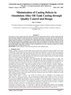
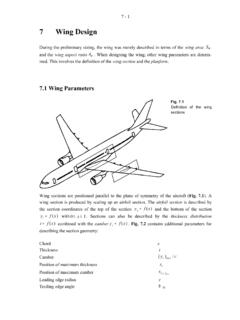
4 AIRFOIL Airfoils are structures with specific geometric shapes that are used to generate mechanical Forces due to the relative motion of the Airfoil and a surrounding fluid. Wind turbine blades use Airfoils to develop mechanical power. The cross-sections of wind turbine blades have the shape of Airfoils . The width and length of the blade are functions of the desired aerodynamic performance, the maximum desired rotor power, the assumed Airfoil properties, and strength considerations. Fig 1- Terminology of Airfoil. Terminology of Airfoil shows in Fig flow over an Airfoil produces a distribution of Forces over the Airfoil surface. The flow velocity over Airfoils increases over the convex surface resulting in lower average pressure on the suction side of the Airfoil compared with the concave or pressure side of the Airfoil.
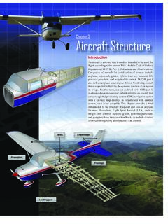
5 Meanwhile, viscous friction between the air and the Airfoil surface slows the air flow to some extent next to the surface. Lift force defined to be perpendicular to direction of the oncoming air flow. The lift force is a consequence of the unequal pressure on the upper and lower Airfoil surfaces. Drag force defined to be parallel to the direction of the oncoming air flow. The drag force is due both to viscous friction Forces at the surface of the Airfoil and to unequal pressure on the Airfoil surfaces facing toward and away from the oncoming flow. Fig 2 shows the Lift and Drag Forces on Airfoil. Fig 2- Lift and Drag Forces . The lift and drag Forces are calculated by the following formula. Lift = (1/2)*rho* CL*c*l*Vrel Drag = (1/2)* * CD*c*l*Vrel Where rho density of air - kg/m c Chord length in meter l Length of the blade element Vrel relative velocity of air in m/s = V (1+ (tpr) ) International Journal of Application or Innovation in Engineering & Management (IJAIEM) Web Site: Email: Volume 4, Issue 4, April 2015 ISSN 2319 - 4847 Volume 4, Issue 4, April 2015 Page 200 AIRFOIL The NACA Airfoils are Airfoil shapes for aircraft wings developed by the National Advisory Committee for Aeronautics (NACA).
6 The shape of the NACA Airfoils is described Using a series of digits following the word NACA . The parameters in the numerical code can be entered into equations to precisely generate the cross-section of the Airfoil and calculate its properties. 4 digit Airfoil specification This NACA Airfoil series is controlled by 4 digits NACA 2412, which designate the camber, position of the maximum camber and thickness. If an Airfoil number is NACA MPXX NACA 2412 M is the maximum camber divided by 100. In the example M=2 so the camber is or 2% of the chord P is the position of the maximum camber divided by 10. In the example P=4 so the maximum camber is at or 40% of the chord. XX is the thickness divided by 100. In the example XX=12 so the thickness is or 12% of the chord. Using PYTHON Python is a widely used general-purpose, high-level programming language.
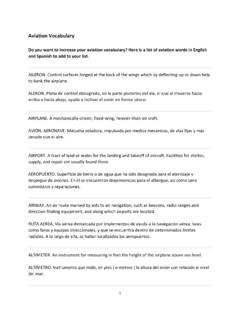
7 Its design philosophy emphasizes code readability, and its syntax allows programmers to express concepts in fewer lines of code than would be possible in languages such as C++ or Java. The language provides constructs intended to enable clear programs on both a small and large scale. Python(x,y) is used for the programming. xlrd library used for the read the excel file which contain data for different NACA Airfoils . The Airfoil profiles selected for the Analysis are NACA0012, NACA4412 and NACA6412. The database contains Airfoils that are designed or used for wind turbine applications. The lift and drag coefficients of the Airfoils , that are based on wind tunnel test, are listed for various angles of attack and Reynolds numbers. Data are taken from the Airfoil tool. Fig 3-5 shows the NACA profile and Table 1-3 shows the data of each.
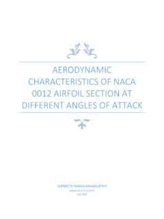
8 (Max thickness at chord. Max camber 0% at 0% chord) Fig 3- NACA0012 Airfoil (Source NACA Airfoil Tool ) Table 1- Sheet1 data NACA0012 Cl & Cd for AOA Reynolds No = 50000 AOA Cl Cd 1 2 3 4 5 6 7 8 International Journal of Application or Innovation in Engineering & Management (IJAIEM) Web Site: Email: Volume 4, Issue 4, April 2015 ISSN 2319 - 4847 Volume 4, Issue 4, April 2015 Page 201 (Max thickness 12% at 30% chord. Max camber 4% at 40% chord) Fig-4 NACA4412 Airfoil (Source NACA Airfoil Tool ) Table 2- Sheet2 data NACA4412 Cl & Cd for AOA Reynolds No = 50000 AOA Cl Cd 1 2 3 4 5 6 7 8 9 10 11 12 13 14 (Max thickness 12% at chord. Max camber 6% at chord) Fig-5 NACA6412 Airfoil (Source NACA Airfoil Tool ) Table 3- Sheet3 data NACA6412 Cl & Cd for AOA Reynolds No = 50000 AOA Cl Cd 1 2 3 4 5 6 7 8 9 10 International Journal of Application or Innovation in Engineering & Management (IJAIEM) Web Site: Email: Volume 4, Issue 4, April 2015 ISSN 2319 - 4847 Volume 4, Issue 4, April 2015 Page 202 Programme to find the Lift and drag Forces for NACA Airfoils .
9 Fig 6 shows the screen layout of Python(x,y) programming and its output. Excel file read by the xlrd package for the Python. Fig 6 - Python programming and output. The Lift and Drag Forces are find out here for different parameter which is shown in Table behavior shown in Fig 7-12. and Drag Forces for the tpr=5, V=8m/s , c=2m & various AOA Table 4- Lift and Drag Forces for various AOA AOA NACA0012 NACA4412 NACA6412 Fl Fd Fl Fd Fl Fd 1 2 3 4 5 6 7 8 9 .. 10 .. 11 .. 12 .. 13 .. 14 .. International Journal of Application or Innovation in Engineering & Management (IJAIEM) Web Site: Email: Volume 4, Issue 4, April 2015 ISSN 2319 - 4847 Volume 4, Issue 4, April 2015 Page 203 Fig 7- NACA0012 Lift & drag Forces for AOA Fig 8 NACA4412 Lift & drag Forces for AOA Fig 9-NACA6412 Lift & drag Forces for AOA International Journal of Application or Innovation in Engineering & Management (IJAIEM) Web Site: Email.
10 Volume 4, Issue 4, April 2015 ISSN 2319 - 4847 Volume 4, Issue 4, April 2015 Page 204 and Drag Forces for the tpr=5, AOA=70 and c=2m & Varying V Table 5- Lift and Drag Forces for various V Velocity NACA0012 NACA4412 NACA6412 Fl Fd Fl Fd Fl Fd 5 6 7 8 9 10 Fig 10-NACA Airfoil Lift & drag Forces for Wind velocity. and Drag Forces for the V =5, AOA=70 and c=2m & Varying tpr. Table 6- Lift and Drag Forces for various tpr tpr NACA0012 NACA4412 NACA6412 Fl Fd Fl Fd Fl Fd 5 6 7 8 Fig 11-NACA Airfoil Lift & drag Forces for Tip speed ratio. International Journal of Application or Innovation in Engineering & Management (IJAIEM) Web Site: Email: Volume 4, Issue 4, April 2015 ISSN 2319 - 4847 Volume 4, Issue 4, April 2015 Page 205 and Drag Forces for the tpr = 5 and c=2m & Varying AOA & V.