Transcription of An Improved Multiband Trap Dipole Antenna
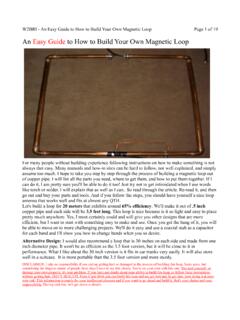
1 An Improved Multiband Trap Dipole AntennaYou need this traps with lower loss, higher Q, increased power-handling capability and four-band coverage!By Al Buxton, W8 NXThis Improved Multiband trap Dipole introduces a new trap design and a change in trap location. The Antenna features double-coaxial- cable -wound traps having lower reactance and a higher quality factor (Q) than earlier coax- cable traps. Because trap loss resistance is determined by trap reactance divided by Q, these enhancements provide a substantial reduction in such losses. Of as much significance, the new traps have a fourfold increase in power-handling capability over that of other coax cable traps (more on that later). Weatherproof performance and the ease of construction of coax- cable traps is Dipole (see Figure 1) operates on 80, 40, 17, and 10 meters; four of our more popular bands. The Dipole is made of #14 stranded copper wire radiating elements, a 1:1 balun, a pair of insulators and a pair of the new traps.
2 Notice the change in trap location. The traps are at the ends of elements rather than 32-foot elements as in a conventional 80 and 40-meter trap Dipole . Trap resonance on the four bands is nonexistent. Because there is no open-switch divorcement action by the traps, the full length of the Antenna radiates on the four bands. Avoiding trap resonance lowers the possibility of trap-voltage breakdown. True resonant-current feed is obtained on the four bands, making the Antenna compatible with either 50 or 75- coaxial- cable feed lines. Fundamental-frequency operation is provided on 80 and 40 meters, and long-wire, odd-harmonic operation on 17 and 10 Antenna is a rewarding and inexpensive project for those of you who like to homebrew your own equipment. I designed the Antenna with a little cut and try using my new Trap and Stub Dipole Antennas for Radio Amateurs computer software package. [1]Figure 1 An Improved 80, 40, 17 and 10-meter trap ConstructionTrap construction is relatively easy, even for those with few manual skills and tools.
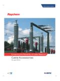
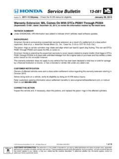
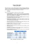
3 Figure 2 is a photograph of a trap; Figure 3 is the trap schematic. Double-coax-wound traps have two parallel windings of coax cable (A and B) rather than a single- cable winding. The two shield windings and center conductors are each connected in parallel. The series loss resistance of the trap dominated by skin effect is essentially halved by the parallel connection. The surface area for convection and heat conduction away from the trap is essentially doubled. Power losses in the polyethylene dielectric of the trap are almost negligible because of the relatively low frequencies involved. July QST: An Improved Multiband Trap Dipole Antenna - Page 1 ARRL 1996 QST/QEX/NCJ CD Ci ht (C) 1997 b Th AiR di R lLI Figure 2 Close-up of a completed trap. Figure 3 Double-coax trap SWR performance of the Antenna at my location, using a 50 to 75- transformer and a 75- feed line, is shown in Figure 4. The Antenna is installed as an inverted V with a 40-foot apex height.
4 Notice the very good performance on 40 meters, where the SWR is less than 2 across the entire band. The Antenna favors the low end of 10 meters, where most of the activity seems to be concentrated. On 17 meters, the SWR is close to 3 across the band, requiring an Antenna tuner to keep the rig happy. The 2:1 SWR bandwidth on 80 meters is 75 kHz, centered on MHz. A good Antenna tuner can extend the operating bandwidth on 80 meters well into the CW portion of the band or into the General class phone QST: An Improved Multiband Trap Dipole Antenna - Page 2 ARRL 1996 QST/QEX/NCJ CD Ci ht (C) 1997 b Th AiR di R lLI Figure 4 SWR plot of the Improved trap measured the Q of these traps at two widely separated low frequencies and extrapolated the results to the higher operating frequencies. This two-frequency extrapolation method solves an otherwise impossible problem of directly measuring the Q of coaxial- cable traps. This approach separates the dielectric losses and the skin-effect ohmic losses of the trap; it assumes the skin-effect losses vary as the square root of frequency, and the dielectric losses vary as the first power of frequency.
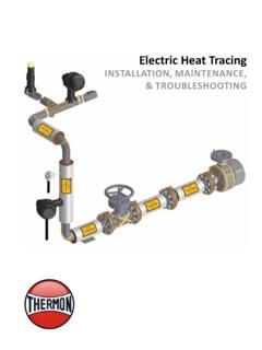
5 The results are shown in Figure 5, where the Q of an RG-59 double-coax trap is compared with the Q of a common RG-59 coax trap. The Q of a common RG-58 coax trap is also shown. The superiority of the double-coax configuration is clearly evident. The superiority of RG-59 over RG-58 is also demonstrated. All traps are tuned to a nominal MHz and are of the optimum Q and length/diameter ratio. As you can see, the double-coax RG-59 configuration has a Q about 18% higher than the common singly wound coax configuration. Figure 5 Trap quality factor, Q, versus calculated the trap losses for the bands covered using Roy (W7EL) Lewallen s EZNEC program. The results are shown in July QST: An Improved Multiband Trap Dipole Antenna - Page 3 ARRL 1996 QST/QEX/NCJ CD Ci ht (C) 1997 b Th AiR di R lLI Table 1. The Antenna was assumed to be horizontally mounted, 40 feet above real ground and using the legal power-output limit of 1500 W PEP. The stray capacitance of the outer shields of the coax traps was simulated as a length of #14 wire hanging down from the outboard end of the traps.
6 The ratio of PEP to average power is assumed to be 2:1, corresponding to ideal two-tone single-sideband modulation. Notice the very high radiation efficiency and negligible trap dissipation on 40, 17 and 10 meters. On 80 meters, however, the Antenna s low height and its shortened length reduce the Antenna input resistance to , making trap loss significant. On 80 meters, the trap Q is 171. The combined loss from both traps equals dB on this band, an insignificant amount. The input-resistance component chargeable to trap loss becomes significant to the extent of dissipating of the input power in the traps as heat. At this power level, there is an average dissipation of W in each trap. The voltage drop across the traps is 2984 V, below the 3400-V rating of the cable . Table 1 Trap Loss SummaryBand (meters)Freq (MHz)Radiation Efficiency (%)Trap Loss (dB)Trap Power Dissipation (W)80 operating experience indicates that common coaxial- cable traps can dissipate 35 W or more without failure.
7 Therefore, I believe that the double-coax traps can dissipate 140 W or more without failure, indicating that the dissipation per trap at the 1500-W PEP level can be handled successfully. Because I lack the necessary amplifier, I haven t confirmed such operation. So far, I ve operated this Antenna only at the 600-W PEP output level of my Yaesu FL-7000 amplifier. (During subsequent ARRL Lab tests, these traps successfully handled a two-tone 1500-W PEP signal for 10 minutes with no signs of stress. Ed.) If any amateur has a theoretical basis for calculation of trap power-dissipation capability, please let me know about it. Details of the trap construction and its connections to the Antenna segments are shown in Figures 6 and 7. Before commencing construction, study the trap details in these figures as well as Figures 2 and 3. The trap resonant frequency is MHz. Trap resonant-frequency tolerance is 50 kHz, permitting selection of a resonant frequency anywhere between and MHz.
8 The band most sensitive to trap-frequency error is 80 meters, where a trap- frequency error of 50 kHz causes an Antenna resonant-frequency error of 30 kHz of the same sign. Thus, if you have a General class ticket and want to be above MHz on 80 meters, it s better to have the trap resonant frequency err on the high side rather than on the low side of MHz. Indeed, General class ticket holders may want to shorten the trap windings by an eighth of a double-turn to set the 80-meter Antenna frequency above MHz. In that case, increase the trap frequency to about MHz. The trap frequencies should be checked with a dip meter and an accurate frequency reference before installing the traps in the Antenna . Errors and changes in the trap s resonant frequency have much smaller effects on the 40, 17, and 10-meter bands than on the 80-meter the Traps Describing how to make the traps is more difficult than making them! See Figures 6 and 7. Each trap consists of double turns of seven-foot lengths of RG-59 (Belden 8241) coaxial cable (A and B) wound on a PVC form.
9 [2] Each form is a length of schedule-40 PVC pipe (three-inch ID PVC pipe). Confirm the OD of the PVC because trap frequency is sensitive to form diameter. Drill two holes at the windings start and end. See Figure 6. The center of the starting hole for winding A is one inch from the end of the form. Stagger the two starting holes relative to each other, using the hole for winding A as the reference location. The B winding starting hole is delayed inch longitudinally and inch along the circumference relative to the B winding starting hole. The fractional number of double-coax turns is 1/8 of a turn less than a full seven turns. Therefore, the ending-turn holes are drilled 1/8 of the circumference ( inches) shy of seven full turns. The staggered relationship at the start of the windings is repeated at the end of the windings. Thus, the end winding hole for winding A lags inches along the circumference behind the start winding hole for winding the hole edges with a sharp utility knife or rattail file to permit the cable to feed easily through the holes.
10 The cable s OD makes for a snug fit in the seven-foot cable lengths leave four inches at each winding end to make the trap pigtails that extend inside the PVC form. Wind the A and B turns simultaneously. Use locking pliers inside the PVC form to firmly hold the two pigtails at the start of the windings. Clamp the far end of the windings in a vise to maintain firm and equal tension on the two cables as you wind them July QST: An Improved Multiband Trap Dipole Antenna - Page 4 ARRL 1996 QST/QEX/NCJ CD Ci ht (C) 1997 b Th AiR di R lLI around the form. Avoid gaps between turns. After placing the turns, insert the cable ends through the end holes. While maintaining tension on the cables, use your fingers and needle-nose pliers to push and pull the cables into the inside of the a sharp utility knife, strip away the last three inches of polyvinyl cover from the pigtails. Avoid cutting the shield braid. Separate the pigtail s shield braid from the dielectric and its inner conductor.