Transcription of An Introduction to Brake Systems
1 Introduction to Brake Systems8/20/2002 P. Gritt110/6/200210/6/2002An Introduction toAn Introduction toBrake SystemsBrake SystemsSAE Brake ColloquiumSAE Brake ColloquiumOctober 6th 2002 October 6th 2002 DaimlerChryslerThis presentation was originally created as a one hour lectureclass. This is not intended to be a stand alone text book onbasic Brake Systems . I have added verbiage to the notespages in an attempt to make the information more useful as abasic starting point for the new Brake is anticipated that going through this will generate as manyquestions as it to Brake Systems8/20/2002 P.
2 Gritt210/6/200210/6/20022 Presented By:Presented By:Paul S. GrittPaul S. GrittBrake EngineeringBrake Engineering--DaimlerChrysler CorporationDaimlerChrysler CorporationIntroduction to Brake Systems8/20/2002 P. Gritt310/6/200210/6/20023 Topics To Be PresentedTopics To Be Presented The basic principles Hydraulic layouts Component function Brake balance Stopping distance Government requirements Customer requirementsIntroduction to Brake Systems8/20/2002 P. Gritt410/6/200210/6/20024 The Basic PrinciplesThe Basic Principles Kinetic energy = heat Newton is always right!
3 F=ma When all else fails see point 2 Introduction to Brake Systems8/20/2002 P. Gritt510/6/200210/6/20025 Energy ConversionEnergy ConversionThe Brake system converts the kineticenergy of vehicle motion intoheatThe Brake system converts the kinetic energy of the movingvehicle into Brake engineer has two enough deceleration to stop the car as quickly as the driverwishes, without exceeding the drivers comfort level with regard topedal effort or pedal the resulting heat energy so as not to damage thebrake system or the rest of the to Brake Systems8/20/2002 P.
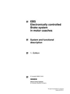
4 Gritt610/6/200210/6/20026 Energy ConversionEnergy ConversionA vehicle weighing 1600 100 kph has kinetic energy of:Stopping the car at .8G takes SecondsThis is equal to 174 kilowatts (233 HP).OR618, equation for the energy conversion is very simple as youcan interesting observation is that a typical car of this size hasan engine with about 90-105 KW (120-140 HP). This meansthat the brakes have to deal with about twice the power ofwhat the engine puts to Brake Systems8/20/2002 P. Gritt710/6/200210/6/20027 Brake Energy as a Function of Speed & WeightBrake Energy as a Function of Speed & Weight0500,0001,000,0001,500,0002,000,00 02,500,0003,000,0003,500,0004,000,000501 00140160200 Speed kphEnergy N-M1600 kg2000 kg2400 kgSince the kinetic energy of a moving vehicle is a function of the square of thespeed.
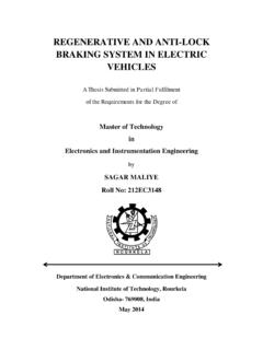
5 The speed from which you wish to stop a vehicle is much more importantthan the mass of the selecting a Brake system the performance of the powertrain must be takeninto to Brake Systems8/20/2002 P. Gritt810/6/200210/6/20028 The Basic EquationThe Basic EquationF=maThe Brake engineer s task!The Brake engineer s task!How do you calculate F?I hope you have not forgotten your freshman to Brake Systems8/20/2002 P. Gritt910/6/200210/6/20029 system ModelSystem Model)(2 FbfRpAmAwRrF + Brake ForceThis picture illustrates the force path from the drivers foot to the tire road interface.
6 Fis the force applied by the driver s footRpis the pedal lever ratioFbis the booster assist forceAmis the area of the master cylinderAwis the area of the front caliper piston is the coefficient of friction of the liningris the effective radius of the caliperRis the loaded radius of the effort or force exerted on the Brake pedal combined with the output of thebooster and the diameter of the master cylinder pistons determines the pressure(psi) in a hydraulic Brake smaller the master cylinder bore diameter is, the higher the pressure will be fora given force on the Brake pedal.
7 However, a smaller diameter master cylinder willrequire more travel of the piston to displace the same amount of fluid as a larger the diameter of the wheel cylinder or caliper piston is, the higher theforce will be pushing on the Brake can sometimes be very difficult to get accurate information about the calipereffective radius and/or the tire loaded to Brake Systems8/20/2002 P. Gritt1010/6/200210/6/200210 There are two layouts of hydraulic Brake Systems usedin cars and light hydraulic split:Also called axle by axle, vertical, and some times blackand white.
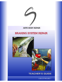
8 Diagonal Split:Also called type of split is only significant in system ConfigurationsHydraulic system ConfigurationsLet's look at the hydraulic circuits used in modern passengercars and light rear wheel drive cars and trucks have front/rear splitsystems. Front wheel drive cars almost always havediagonally split front suspension design of front wheel drive vehicles,(small positive or a negative scrub radius) allows the use ofdiagonal split hydraulic to Brake Systems8/20/2002 P. Gritt1110/6/200210/6/200211 Front/rear Hydraulic SplitFront/rear Hydraulic SplitFront AxleFront AxleRear AxleRear AxleThis is a diagram of a basic front-rear split hydraulic system .
9 Notice that there is one line from the master cylinder to the rear axlebrakes and one line to the front axle brakes. You might also notice that the line to the frontbrakes comes fromthe rear outlet of the master cylinder, and the line to the rear brakes comesfrom the front outlet of the master cylinder. This can cause a lot ofconfusionwhen discussing Brake solution to this Semantic problem is to use the technically correct terms fordescribing master cylinder hydraulic circuit that is closest to the open end of the master cylinder(alsoclosest to the power Brake unit and the driver) is alwaysreferred to as the primary circuit.
10 The circuit closest to the closed end of the master cylindercastingisalwaysreferredtoasthe secondary circuit. This nomenclatureshould be used regardless of how the hydraulic lines of a vehicle are connected tothe rest of the Brake to Brake Systems8/20/2002 P. Gritt1210/6/200210/6/200212 Diagonal Split Hydraulic SystemDiagonal Split Hydraulic SystemRight frontleft rearLeft frontright rearSince there is one line to each Brake a diagonal split systemrequires more tubing and more connections than a front rearsplit distinction between front and rear hydraulic circuits ormaster cylinder outlets becomes meaningless to Brake Systems8/20/2002 P.