Transcription of An introduction to pipe jacking and microtunnelling
1 Pipe jacking AssociationAn introduction to pipe jacking and microtunnelling2An introduction to pipe jacking and microtunnellingCopyright Pipe jacking AssociationISBN 978-1-5272-0341-9 All rights reserved. No part of this publication may be reproduced, stored in a retrieval system, or transmitted in any form or by any means, electronic, photocopy, recording or otherwise, without the prior permission of the the Association does its best to ensure that any advice, recommendations or information it may give is accurate, no liability or responsibility of any kind (including liability for negligence) is accepted by the Association its servants or agents, in this by the Pipe jacking : January 2017 Price: introduction to pipe jacking and microtunnellingContents2a) Table comparing the environmental aspects and carbon savings of open trench and pipe jacked sewer construction at two typical sewer diameters481 THE PIPE jacking TECHNIQUE2 APPLICATIONS AND BENEFITS3a) Diagram showing typical ground information required for design and costing3b) Table of parameters to be considered in relation to each soil type3c) Table illustrating ground treatment and face support methods for varying ground conditions103 SITE INVESTIGATION AND INFORMATION REQUIRED ON SOIL CONDITIONS4a) Table: Design of working shafts in dry ground4b) Table.
2 Design of working shafts in wet ground4c) Table of indicative jacking lengths achievable between shafts for mechanised drives4d) Guidelines for curved drives4e) Table illustrating pipe jacking excavation methods for dry and wet ground134 DESIGN AND CONSTRUCTION METHODS20225 PIPE jacking PIPES6 jacking LENGTHS, LOADS AND TOLERANCESAn overview of pipejacking and microtunnelling and its benefitsDifferent pipe materials and secondary linings and their uses1 The pipe jacking techniquePipe jacking / microtunnelling * is a non-disruptive method of installing utility tunnels and conduits by thrusting pipes through the ground as controlled excavation is undertaken at the face. Pipes manufactured in a variety of materials to include concrete, clay, grp and steel can be jacked and standard pipe diameters generally range from 150mm to 2,400mm, or greater when required.
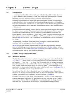
3 jacking lengths achievable can be considerably in excess of 1km depending on pipe diameters, ground conditions and excavation methods. Drive lengths are only limited by practical engineering considerations and economics and drives either in a straight line or to a radius or a series of radii are readily jacking can deliver environmental benefits in excess of 75% as measured by reduced carbon emissions compared to disruptive open-cut construction, which requires considerably greater amounts of excavation and substantial backfill material. Long-term damage to existing installed infrastructure is also minimised.* microtunnelling - originally used to describe the construction of fully automated non man entry pipe jacked tunnels in smaller diameters, the term is now also sometimes applied to fully automated pipe jacks in larger diameters which may be controlled from above introduction to pipe jacking and microtunnelling1 THE PIPE jacking TECHNIQUET ypical pipe jacking arrangementEnvironmental benefits - carbon emissions reduced by up to 75%Undisturbed soilUndisturbed soilImported backfillSurround beddingPIPEC arriagewayPIPE JACKINGOPEN CUTTUNNEL BORING MACHINE (TBM)CUTTER BOOMBACKACTEREARTH PRESSURE BALANCE (EPBM)
4 PRESSURISED SLURRY5An introduction to pipe jacking and microtunnelling1 THE PIPE jacking TECHNIQUET ypical microtunnelling arrangementA number of types of mechanical excavation systems are available and these are similar to those employed in other forms of tunnelling. Shields, excavation and face support can be provided for a wide variety of ground conditions. Construction tolerances are comparable with other tunnelling methods, and the pipe jacking method generally requires less overbreak than segmental tunnels and provides ground support and reduces potential ground pipe jacking technique and its components have been subject to extensive and ongoing research atleading UK universities including both Oxford and Cambridge. This has included model and full scale testing of pipes and joints and the effects of lubrication and soil conditioning on the pipe jacking process.
5 In order to install a pipeline using this technique, thrust and reception pits are constructed, usually at manhole positions. The dimensions and construction of a thrust pit vary according to the specific requirements of any drive with economics being a key factor. Pit sizes will vary according to the excavation methods employed, although these can be reduced if required by special thrust wall is constructed to provide a reaction against which to jack. In poor ground, piling or other special arrangements may have to be employed to increase the reaction capability of the thrust wall. Where there is insufficient depth to construct a normal thrust wall, for example through embankments, the jacking reaction has to be resisted by means of a structural framework having adequate restraint provided by means of piles, ground anchors or other such methods for transferring horizontal ensure that the jacking forces are distributed around the circumference of a pipe being jacked, a thrust ring, mounted on the jacking rig, is used to transfer the loads.
6 The jacks are interconnected hydraulically to ensure that the thrust from each is the same. The number of jacks used may vary because of the pipe size, the strength of the jacking pipes, the length to be installed and the anticipated frictional reception pit of sufficient size for removal of the jacking shield is normally required at the completed end of each drive. The initial alignment of the pipe jack is usually controlled by accurately positioning guide rails within the thrust pit on which the pipes are laid. To maintain accuracy of alignment during pipe jacking , it is necessary to use a steerable shield, which must be frequently checked for line and level from a fixed reference. For short or simple pipe jacks, these checks can be carried out using traditional surveying equipment. Rapid excavation and remote control techniques require sophisticated electronic guidance systems using a combination of lasers and screen based computer the pipejack or microtunnel is carried out below the water table it is usual to incorporate a headwall and seal assembly within each thrust and reception use of these items prevents ingress of ground water and associated ground loss, and retains annular introduction to pipe jacking and microtunnelling1 THE PIPE jacking TECHNIQUE7An introduction to pipe jacking and microtunnelling1 THE PIPE jacking TECHNIQUET hrust pit set-upJacks and thrust ringComputer guidance systems for pipe jacking and microtunnelling2 Applications and benefitsTechnical benefits associated with pipe jacking are.
7 Inherent strength of lining Smooth internal finish giving good flow characteristics No requirement for secondary lining Speed of installation Considerably less joints than a segmental tunnel Prevention of ground water ingress by use of pipes with sealed flexible joints Provision of invert channels in larger pipes to contain the dry weather flow of a sewer in a combined system Less risk of settlement Minimal surface disruption Minimal reinstatement Reduced requirement for utilities diversions in urban areas8An introduction to pipe jacking and microtunnelling2 APPLICATIONS AND BENEFITSTECHNICAL BENEFITSThe major applications for pipe jacking and microtunnelling include new sewerage and drainage construction, sewer replacement and lining, gas and water mains, oil pipelines, electricity and telecommunications cable installation, and culverts.
8 Special applications include the installation of rectangular or circular sections for pedestrian subways, road underpasses and bridge technique can be used to negotiate obstacles such as motorways, railways, rivers, canals, buildings and airfields in the path of pipe laying projects; to minimise the surface disruption frequently associated with open cut pipe laying methods in urban areas; or simply to provide a permanent underground tunnel jacking is primarily used as an alternative to open cut excavations or other tunnelling methods. Significant lengths are attainable at larger diameters using mechanised techniques. Reference should be made to Tables 4c and 4d for specific methods are available to cope with both cohesive and non-cohesive soils in dry or water bearing conditions. Excavation techniques are also available for jacking through rock or mixed ground conditions, including cobbles and introduction to pipe jacking and microtunnelling2 APPLICATIONS AND BENEFITSPipe jacking is an inherently safer method of working than open trench construction or traditional segmental tunnelling.
9 When considering the risks associated with deep, large section, open excavations, Health and Safety Executive guidance suggests these risks should be reduced if appropriate using trenchless technology to avoid the need to excavate the trench in the first place . Given gang size differences between the techniques and the resulting reduction in man-hours, the incidence of accidents are less with pipe jacking . There is also significant reduction in the risk of injury as a result of utility strikes and interface with the are substantial environmental benefits to be gained by the use of pipe jacking techniques when compared with the traditional open trench approach. Typically the trenchless method will reduce the quantities of incoming and outgoing materials, with a consequent reduction in tipping of spoil and quarrying of imported stone fill.
10 This in turn leads to reduced vehicle movements and subsequently less associated table below compares the environmental aspects of open trench and pipe jacked sewer construction at two typical sewer diameters. The comparison assumes that excavated spoil is removed from site to a licensed tip, and that any resultant void after the pipe has been installed is replaced by imported stone backfill overlain by a coated stone surface reinstatement. Since manholes and the delivery of pipeline materials are common to both construction methods, for comparison their environmental effects can be a result of the foregoing the carbon impact is significantly reduced, particularly on urban main drainage and flood relief schemes and this can be readily assessed using the carbon calculator on the PJA website. This carbon calculator was developed by the Transport Research Laboratory and verified by the Water Research many cases the use of pipe jacking techniques instead of open trenching will contribute positively towards workplace safety, the interface with the general public, and the local and wider BENEFITSENVIRONMENTAL BENEFITS600mm ID pipeline4m deep, 100m length1200mm ID pipeline4m deep, 100m lengthAspectOpen trenchTrenchlessOpen trenchTrenchlessExcavated width1400mm(trench width)760mm(OD of jacking pipe)2350mm(trench width)1450mm(OD of jacking pipe)Reinstatement width1700mmNone2650mmNoneExcavated volume per metre of stone fill and coated stone per metre of tonnesNoneNumber of 20 tonne lorry loads per 100m pipeline (muck away and imported stone)136822021 Tonnes CO2 )