Transcription of AN, MS, NAS Bolts - cardinalmfg.com
1 AN, MS, NAS Bolts Most Bolts used in aircraft structures are either (a) general-purpose, (b) internal-wrenching or (c) close-tolerance AN, NAS, or MS Bolts . Design specifications are available in MIL-HDBK-5, USAF 1-1A-8, or Navy NAVAIR 01-1A-8. References should be made to military specifications and industry design standards such as NAS, the Society of Automotive Engineers (SAE), and Aerospace Material Standards (AMS). General purpose aircraft structural Bolts manufactured in accordance with the AN3 20 standards are commonly high strength 8740 alloy steel with a minimum tensile strength around 125 000 PSI, but other steel alloys are included in the specification. The standard Bolts have hexagonal heads, are centerless ground and roll threaded after heat treatment, then cadmium plated and are used in shear or tension applications. The bolt head and/or shank may have holes drilled for safety wire or cotter pins.
2 Aluminum Bolts are also included in the specification but such Bolts are unlikely to be used in a structural role in a light aircraft. AN3 20 Bolts are identified by a multi-part code: Firstly the AN specification identity, then One or two numbers that indicate the shank diameter in 1/16 inch increments starting at AN3 [3/16"] and ending at AN20 [1 1/4"], which may be followed by A dash indicating the material is the standard cadmium plated 8740 or 4037 alloy steel, otherwise one or two letters for the material ( 'C' indicates CRES, "DD" is 2024 aluminum.) Then, if the hexagonal head is drilled for safety wire, the letter 'H' One or two numbers which indicates the length of the shank from under the head to the tip in 1/8 inch increments, if two numbers the first indicates whole inches and the second indicates the 1/8 inch increments ( 23 indicates a shank length of 2 3/8" but there may be variations from this system), then The letter 'A' indicating the bolt shank is not drilled and thus intended for use with a self-locking nut (which is the norm); the letter is absent if the shank is drilled for castle nut and cotter pin locking.
3 For example: AN6-H7A AN6 denotes the specification for general purpose hexagonal head Bolts with a 3/8" [6/16"] diameter shank The dash indicates the material is the standard cadmium plated alloy steel H indicates the bolt head is drilled for safety wire 7 = 7/8 inch shank length and A = indicates the shank is not drilled. Bolt threads. The standard aircraft thread is the 'unified national' form either in the fine [UNF] series or the coarse [UNC] series. Both series are based on a 60 thread; that is if the thread is viewed in cross section each thread forms an equilateral triangle but with the roots and crests of the threads rounded during the rolling process to avoid sharp corners and thus minimize stress concentrations. The coarse series have fewer threads per inch [TPI] for the same bolt diameter. The AN3 20 Bolts use only the UNF threads; the AN3 bolt has 32 TPI, the AN4 is 28 TPI, AN5 and AN6 are 24 TPI, AN7 and AN8 are 20 TPI.
4 Thread length and grip. The threaded length of AN Bolts is about 3/8" for AN3, 7/16" for AN4, 1/2" for AN5 and 9/16" for AN6 AN8. The grip is the shank length minus the threaded length, which for the AN6-H7A bolt would be 7/8" shank length minus 9/16" thread length = 5grip. Thus an AN3-4 bolt would have a grip of only 1/8" and might, at first glance, present the appearance of a fully threaded shank. The threaded length should not be subject to shear loads. The specification allows shank lengths to be from 1/32 to 3/32 inches longer than the nominal length. /16" In general, bolt grip lengths of a fastener are the thickness of the material the fastener is designed to hold when two or more parts are being assembled. Bolts of slightly greater grip length may be used, provided washers are placed under the nut or bolt head. The maximum combined height of washers that should be used is 1/8 inch.
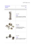
5 This limits the use of washers necessary to compensate for grip, up to the next standard grip size. All bolt installations, which involve self-locking or plain nuts, should have at least one thread at the end of the bolt protruding through the nut. Only the unthreaded portion of the shank the grip should carry shear loads, so a maximum of one or inner end threads are acceptable within the grip length, though the nut should not be run down to the inner end of the threaded length. Aircraft Bolts may be identified by code markings on the bolt heads. These markings generally denote the material of which the bolt is made, whether the bolt is a standard AN-type or a special-purpose bolt, and sometimes include the manufacturer. a. AN standard steel Bolts are marked with either a raised cross or asterisk [most of those pictured], corrosion resistant steel is marked by a single dash [row 1, number 4], and AN aluminum-alloy Bolts are marked with two raised dashes [row 3, number 5].
6 B. Special-purpose Bolts include high - strength , low- strength , and close-tolerance types. These Bolts are normally inspected by magnetic particle inspection methods. Typical markings include SPEC (usually heat-treated for strength and durability) [row 2, number 5] , and an aircraft manufacturer s part number stamped on the head [row 3, number 1]. Bolts with no markings are low strength . Close-tolerance NAS Bolts are marked with either a raised or recessed triangle [row 3, number 4]. The material markings for NAS Bolts are the same as for AN Bolts , except they may be either raised or recessed. Bolts requiring non-destructive inspection (NDI) by magnetic particle inspection are identified by means of colored lacquer, or head markings of a distinctive type. Bolt holes, particularly those of primary connecting elements, have close tolerances. Generally, it is permissible to use the first-lettered drill size larger than the nominal bolt diameter, except when the AN hexagon Bolts are used in light-drive fit (reamed) applications and where NAS close-tolerance Bolts or AN clevis Bolts are used.
7 A light-drive fit can be defined as an interference of inch for a 5/8 inch bolt. Bolt holes should be flush to the surface, and free of debris to provide full bearing surface for the bolt head and nut. In the event of over-sized or elongated holes in structural members, reaming or drilling the hole to accept the next larger bolt size may be permissible. Care should be taken to ensure items, such as edge distance, clearance, and structural integrity are maintained. There are a number of names ( Bolts , screws, machine screws, set screws, cap screws) for headed, external screw threaded fasteners designed either (a) for use with an internally threaded nut to clamp two or more parts together or (b) to clamp one or more parts to another internally threaded metal body. Generally it can be said that fasteners tensioned by turning a threaded nut are Bolts while those tensioned by turning the head are screws, however there is a class of bolt, often referred to as 'engine Bolts ', where the joint is tensioned by turning the bolt head to screw it into an internally threaded metal body.
8 Machine/cap screws are threaded for their full length and are manufactured from carbon steels; structural screws have an unthreaded grip length and are made from alloy steels. In this section we will concentrate on bolt and nut applications in airframe structures. There are two commonly used structural bolted joint designs, one type where the high tensile strength of the bolt shank is used to clamp members together and the joint functionality relies on the surface friction between the members rather than the bolt shank; the joint will hold as long as the friction force is greater than any shear force applied. The other joint type is where the joint primarily relies on the shear strength of the bolt shank, such as seen in aluminum tubular struss structures, and there is only sufficient tensile load applied to the bolt/nut to prevent movement after locking.
9 If a turning force or torque is applied with a wrench to the nut of a bolt and nut pair already 'snugged up' holding all joint interfaces in intimate contact but with little or no tension in the bolt the under surface of the bolt head and the inner surface of the nut (or intermediate washers if fitted) will apply a compressive force to the members, clamping them together. Dependent on the stiffness of the joint members the periphery of that compressive effect extends to around 4 5 times the diameter of the bolt shank. The greater the torque applied to the nut the greater the tension in the bolt and the greater the compression in the members (or the crushing force applied to the member/s and any intermediate sealing gasket). 'Hard' joints may only require the nut to be rotated through a 30 angle from the snugged position to achieve the full torque, a 'soft' gasketed joint may require a rotation of two full turns from the snugged position.
10 Referring to the stress-strain diagram in the properties of metals module it can be seen that as long as the tensile stress in the bolt is less than the yield strength the resulting bolt stretch [the strain] will stay within the elastic region. While that tension continues the bolt elasticity [the potential energy] will apply the clamping force holding the joint together. This clamping force is called the pre-load or pre-tension, which, for a high -stress joint (such as a propeller hub/crankshaft flange joint) might be set at 70% or more of the bolt yield strength the position indicated by the small green cross in that stress-strain diagram. Because bolt threads act as stress concentrators permanent deformation will occur at loads a little below yield strength maybe around the 95% level. This is termed the bolt proof strength , proof stress or proof load.