Transcription of AN0021: Analog to Digital Converter - Silicon Labs
1 AN0021: Analog to Digital Converter (ADC)This application note describes how to use the Analog to DigitalConverter (ADC) of EFM32 Gecko Series 0 and 1 devices to con-vert an Analog input voltage to a Digital value. Many aspects ofthe ADC, including inputs, references, and the different operatingmodes are described. Calibration routines for offset and gain arealso provided software examples show how to use the different operating modes of theADC. The example projects are configured for the EFM32 Gecko Series 0 and 1 devi-ces, but can easily be ported to other EZR32 Wireless MCU and EFR32 WirelessGecko devices by changing the project simplicity, EFM32 Wonder Gecko, Gecko, Giant Gecko, Leopard Gecko, TinyGecko, Zero Gecko, and Happy Gecko are a part of the EFM32 Gecko Series Wonder Gecko, Leopard Gecko, and Happy Gecko are a part of the EZR32 Wireless MCU Series Pearl Gecko and Jade Gecko (and future devices) are a part of the EFM32 Gecko Series Blue Gecko, Flex Gecko, and Mighty Gecko are a part of the EFR32 WirelessGecko Series POINTS There are new ADC features in EFM32 Gecko Series 1 devices.
2 This document discusses ADC operationand advanced features. The ADC supports offset and gaincalibration. This application note includes: This PDF document Source files Example C-code Multiple IDE + | Smart. Connected. 1. Analog to Digital IntroductionThe EFM32 Gecko ADC is a Successive Approximation Register (SAR) architecture. The maximum resolution is 12 bits, which canachieve one million samples per second (Msps). The integrated input MUX can select the ADC input from external pins or internal sig-nals. With PRS and DMA, the ADC can operate without CPU intervention, minimizing current consumption or allowing the core to doother work. The ADC can be clocked at different speeds and run using different warm-up modes to reduce the energy consumptioneven application note discusses general operation and usage of the ADC. In addition, advanced features and power saving techniquesare described. Software examples of ADC operation both with DMA and PRS are included.
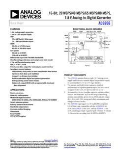
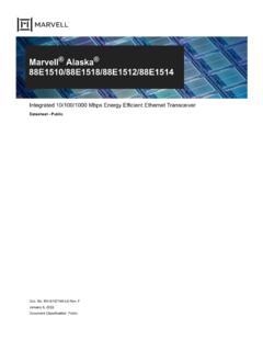
3 Offset and Gain Calibration of the ADC isalso described and included in the software extremely low power periodic ADC sampling, a software example that enters Energy Mode 2 (EM2) between each ADC sample isalso included. This is the best way to do low power ADC sampling for sampling frequencies below a couple of : Analog to Digital Converter (ADC) Analog to Digital | Smart. Connected. | OverviewThe Figure ADC Overview of EFM32 Giant Gecko on page 2 and Figure ADC Overview of EFM32 Pearl Gecko on page 3illustrate the internal connections of the inputs, reference selection, and VVDDS equencerResult buffer+-ControlADCn_SINGLEDATAADCn_SCAND ATAADCn_SCANCTRLADCn_CTRLADCn_SINGLECTRL P rescalerADC_CLKHFPERCLKADCnDAC1 Oversampling filterADCn_CMDADCn_STATUS2x(VDD-VSS)5 V differentialVref/2 Figure ADC Overview of EFM32 Giant GeckoAN0021: Analog to Digital Converter (ADC) Analog to Digital | Smart. Connected. | 2 APORT1 XTEMPVSSVSSAPORT2 XSequencer+-ControlADCn_SINGLEDATAADCn_S CANDATAADCn_SCANCTRLXADCn_SINGLECTRLADCn _SCANCTRLP rescalerADC_CLKHFPERCLKADCn ADCn_SINGLECTRLXADCn_STATUSASYNCCLKADCn ADCCLKMODEO versampling filterSINGLESAMPLE FIFOSCAN SAMPLE FIFOSCAN INPUTIDADCn_CMDADCn_CTRLADCn_CMPTHRADCn_ BIASPROGINN_MUXINP_MUXAPORT3 XAPORT4 XAPORT0 XAVDDDVDDDECOUPLEIOVDDvdd_muxAPORT1 YAPORT2 YAPORT3 YAPORT4 YAPORT0 YDAC0 OUT0 DAC0 OUT1 ADCn_EXTP ADCn_EXTNC onversion clock (adc_clk_sar)ADC_CLKF igure ADC Overview of EFM32 Pearl GeckoSome new ADC features (see the list below) are added in the EFM32 Gecko Series 1 and EFR32 Wireless Gecko Series 1 devices.
4 Externally controllable conversion start time using PRS in TIMED mode Can be run during EM2 and EM3, waking up the system upon various enabled interrupts Can be run during EM2 and EM3 with DMA enabled to pull data from the FIFOs without waking up the system Automated clock gating to save power when not converting Supports up to 144 external input channels and 11 internal inputs Includes temperature sensor and random number generator function Programmable scan sequence Up to 32 configurable samples in scan sequence Four deep FIFOs to store conversion data along with a channel ID and an option to overwrite old data when full Programmable watermark (DVL) to generate a SCAN interrupt Supports window compare function Programmable single-channel conversion Four deep FIFOs to store conversion data along with an option to overwrite old data when full Programmable watermark (DVL) to generate a SINGLE interrupt Supports window compare function Programmable and preset input full scale (peak-to-peak) range (VFS) with selectable reference sources User-programmable dividers for flexible VFS options from internal, external, or supply voltage reference sources Interrupt generation and/or a DMA request when Programmable number of converted data available in the single FIFO (also generates DMA request)AN0021: Analog to Digital Converter (ADC) Analog to Digital | Smart.
5 Connected. | 3 Programmable number of converted data available in the scan FIFO (also generates DMA request) Single FIFO overflow or underflow Scan FIFO overflow or underflow Latest Single conversion tripped compare logic Latest Scan conversion tripped compare logic Analog over-voltage interrupt Programming Error interrupt due to APORT Bus Request conflict or NEGSEL programming errorAN0021: Analog to Digital Converter (ADC) Analog to Digital | Smart. Connected. | 42. General Clock SelectionThe ADC has an internal pre-scaler which can divide the selected ADC conversion clock source. Any factor between 1 and 128 can bechosen by writing a value between 0 and 127 to the PRESC bit field in the ADCn_CTRL symbols for different clock sources can be found in Figure ADC Overview of EFM32 Giant Gecko on page 2 and ADC Overview of EFM32 Pearl Gecko on page ADC Clock SelectionItemEFM32 Gecko Series 0 and EZR32 Series 0 EFM32 Gecko Series 1 and EFR32 WirelessGecko Series 1 ADC peripheral clock source (register in-terface)HFPERCLKHFPERCLKADC conversion clock sourceHFPERCLKThe ADC_CLK is selected by ADCCLKMODE bitfield in the ADCn_CTRL register HFPERCLK (ADCCLKMODE = 0) ASYNCCLK (ADCCLKMODE = 1)ASYNCCLK source Selected by ADC0 CLKSEL bit field in theCMU_ADCCTRL register Disabled (ADC0 CLKSEL = 0) AUXHFRCO (ADC0 CLKSEL = 1) HFXO (ADC0 CLKSEL = 2) HFSRCCLK (ADC0 CLKSEL = 3)ADC conversion clock frequencyADC_CLK = HFPERCLK / (1 to 128)Range is from 32 kHz to 13 MHzadc_clk_sar = ADC_CLK / (1 to 128)
6 Range is from 32 kHz to 16 MHzClock source for ADC operation in EM2and EM3 AUXHFRCO (ASYNCCLK) is the only availableoption during EM2 or Input SelectionThe external inputs can either be selected as single-ended inputs or combined to allow for differential inputs (see Analog Port(APORT) for ADC). The DIFF bit field in the ADCn_SINGLECTRL or ADCn_SCANCTRL register enables differential ADC input signals are shielded fairly well against other noisy signals within the EFM32 Gecko. If high ADC accuracy is needed, it isadvisable not to use any of the unused ADC input pins for noise-inducing activities, such as serial Single-Ended ModeIn single-ended mode the input signal is measured with ground as the negative input. The voltage span between 0 V and the selectedreference is divided in small steps according to the selected result is an unsigned number between 0 and 2resolution - 1, indicating where the input voltage is located in the span between groundand the reference : Analog to Digital Converter (ADC)General | Smart.
7 Connected. | Differential ModeIn differential mode the measured value is the difference between two inputs. Since one input is defined as the positive input and theother is defined as the negative input, the difference can be positive or negative depending on which input is higher. As a result, theconversion result is a signed number represented in two's complement form. If the negative input is higher than the positive input, theconverted value is negative (see Differential Inputs and Single and Scan Conversion with Differential Inputs). Note that the ADCcannot convert negative voltages in reference to ADC Input SelectionItemEFM32 Gecko Series 0 and EZR32 Series 0 EFM32 Gecko Series 1 and EFR32 WirelessGecko Series 1 External inputs for Single-Ended modeUp to 8, fix on pins PD0 PD7Up to 144 through APORTE xternal inputs for DifferentialmodeUp to 8, fix on pins PD0 PD7 Two neighboring inputs are used in differentialmode, for instance channel 0 and channel 1 isone differential pair, channel 2 and channel 3another The lowest channel number is the positive dif-ferential inputUp to 72 through APORTI nternal inputs6Up to 11 Input filteringLow pass RC filter or an internal decoupling ca-pacitor Temperature sensorSet INPUTSEL bit field in the ADCn_SIN-GLECTRL register to TEMPSet POSSEL bit field in the ADCn_SINGLECTRL register to TEMPO ffset calibrationSet INPUTSEL bit field in the ADCn_SIN-GLECTRL register to DIFF0 (short between posi-tive and negative inputs)
8 Set POSSEL and NEGSEL bit fields in theADCn_SINGLECTRL register to VSSAN0021: Analog to Digital Converter (ADC)General | Smart. Connected. | Reference SelectionTo convert an Analog voltage to a Digital value, the ADC needs a reference voltage to which it compares the incoming Analog the ADC cannot measure voltages larger than the reference voltage, the reference voltage should be above the maximum expec-ted measured selected reference source is combined with internal circuitry to produce the full-scale voltage (VFS) for the Converter . VFS is thefull input range of the Converter , from the lowest possible input voltage to the highest. For single-ended conversions, the input range onthe selected positive input is from 0 to VFS. For differential conversions, the input to the Converter is the difference between the positiveand negative input selections. The ADC conversion result ranges from -VFS/2 to + maximum and minimum input voltage which the ADC can recognize at any external pin is limited to the supply voltages.
9 If VFS isconfigured to be larger than the supply range (for example, VFS configured to 5 V when operating on a V supply), the full ADCrange is not ADC cannot measure negative voltages or voltages larger than the reference voltage. As a result, it is important to keep both in-puts within the electrical limits of the ADC Reference SelectionItemEFM32 Gecko Series 0 and EZR32 Series 0 EFM32 Gecko Series 1 and EFR32 WirelessGecko Series 1 Internal bandgap reference V V (supply voltage > V) 5 V differential (supply voltage > V) V V 5 V differentialInternal reference VDD Unbuffered 2 x VDD AVDD 2 x AVDDE xternal single-ended refer-encePin PD6 as inputUse ADCn_EXTP pin as inputExternal differential reference Use pin PD6 as positive input Use pin PD7 as negative input Reference = 2 x (PD6 PD7) Use ADCn_EXTP pin as positive input Use ADCn_EXTN pin as negative input Reference = 2 x (ADCn_EXTP ADCn_EXTN)GPBIASACC bit field of theADCn_BIASPROG register Set to 0 (HIGHACC) when an internal bandgapreference source is used Set to 1 (LOWACC) when AVDD or an externalpin reference is usedAN0021: Analog to Digital Converter (ADC)General | Smart.
10 Connected. | ConversionsA conversion consists of acquisition and approximation phases. The input is sampled in the acquisition phase before it is converted todigital representation during the approximation phase. The acquisition time can be configured independently for scan sequence andsingle channel conversions by setting AT bit field in the ADCn_SINGLECTRL or ADCn_SCANCTRL symbols for different clock sources can be found in Figure ADC Overview of EFM32 Giant Gecko on page 2 and ADC Overview of EFM32 Pearl Gecko on page ADC ConversionsItemEFM32 Gecko Series 0 and EZR32 Series 0 EFM32 Gecko Series 1 and EFR32 WirelessGecko Series 1 ADC_CLKPre-scaled HFPERCLKHFPERCLK or ASYNCCLKadc_clk_sar Pre-scaled ADC_CLKA cquisition time (AT)1 to 256 (integer power of 2) ADC_CLK cycles 1 to 256 (integer power of 2) adc_clk_sar cyclesMinimum acquisition time forVDD/32 s Minimum acquisition time forthe internal temperature sensor2 sAT bit field of the ADCn_SINGLECTRL orADCn_SCANCTRL register should be set to avalue of 9 (256 adc_clk_sar cycles)