Transcription of AN10441 Level shifting techniques in I2C-bus design
1 AN10441 Level shifting techniques in I2C-bus designRev. 01 18 June 2007 Application noteDocument informationInfoContentKeywordsI2C-bus, Level shiftingAbstractLogic Level shifting may be required when interfacing legacy devices with newer devices that use a smaller geometry process. For bidirectional bus systems like the I2C-bus , such a Level shifter must also be bidirectional, without the need of a direction control signal. The simplest way to solve this problem is by connecting a discrete MOS-FET to each bus NXP 2007. All rights noteRev. 01 18 June 2007 2 of 7 Contact informationFor additional information, please visit: sales office addresses, please send an email to: SemiconductorsAN10441 Level shifting techniques in I2C-bus design Revision historyRevDateDescription0120070618 application note ; initial NXP 2007.
2 All rights noteRev. 01 18 June 2007 3 of 7 NXP SemiconductorsAN10441 Level shifting techniques in I2C-bus design1. IntroductionPresent technology processes for integrated circuits with clearances of m and less limit the maximum supply voltage and consequently the logic levels for the digital I/O signals. To interface these lower voltage circuits with existing 5 V devices, a Level shifter is needed. For bidirectional bus systems like the I2C-bus , such a Level shifter must also be bidirectional, without the need of a direction control signal. The simplest way to solve this problem is by connecting a discrete MOS-FET to each bus Bidirectional Level shifter for Fast-mode and Standard-mode I2C-bus systemsIn spite of its surprising simplicity, such a solution not only fulfils the requirement of bidirectional Level shifting without a direction control signal, it also: isolates a powered-down bus section from the rest of the bus system protects the lower voltage side against high voltage spikes from the higher-voltage bidirectional Level shifter can be used for both Standard-mode (up to100 kbit/s) or in Fast-mode (up to 400 kbit/s) I2C-bus systems.
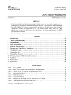
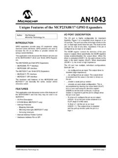
3 It is not intended for Hs-mode systems, which may have a bridge with a Level shifting Connecting devices with different logic levelsDifferent voltage devices could be connected to the same bus by using pull-up resistors to the supply voltage line. Although this is the simplest solution, the lower voltage devices must be 5 V tolerant, which can make them more expensive to manufacture. By using a bidirectional Level shifter, however, it is possible to interconnect two sections of an I2C-bus system, with each section having a different supply voltage and different logic levels . Such a configuration is shown in Figure 1. The left low-voltage section has pull-up resistors and devices connected to a V supply voltage; the right high-voltage section has pull-up resistors and devices connected to a 5 V supply voltage.
4 The devices of each section have I/Os with supply voltage related logic input levels and an open-drain output Level shifter for each bus line is identical and consists of one discrete N-channel enhancement MOS-FET; TR1 for the serial data line SDA and TR2 for the serial clock line SCL. The gates (g) have to be connected to the lowest supply voltage VDD1, the sources (s) to the bus lines of the lower-voltage section, and the drains (d) to the bus lines of the higher-voltage section. Many MOS-FETs have the substrate internally connected with its source, if this is not the case, an external connection should be made. Each MOS-FET has an integral diode (n-p junction) between the drain and NXP 2007. All rights noteRev.
5 01 18 June 2007 4 of 7 NXP SemiconductorsAN10441 Level shifting techniques in I2C-bus design Operation of the Level shifterThe following three states should be considered during the operation of the Level shifter:1. No device is pulling down the bus line. The bus line of the lower-voltage section is pulled up by its pull-up resistors Rp to V. The gate and the source of the MOS-FET are both at V, so its VGS is below the threshold voltage and the MOS-FET is not conducting. This allows the bus line at the higher-voltage section to be pulled up by its pull-up resistor Rp to 5 V. So the bus lines of both sections are HIGH, but at a different voltage A V device pulls down the bus line to a LOW Level . The source of the MOS-FET also becomes LOW, while the gate stays at V.
6 VGS rises above the threshold and the MOS-FET starts to conduct. The bus line of the higher-voltage section is then also pulled down to a LOW Level by the V device via the conducting MOS-FET. So the bus lines of both sections go LOW to the same voltage A 5 V device pulls down the bus line to a LOW Level . The drain-substrate diode of the MOS-FET the lower-voltage section is pulled down until VGS passes the threshold and the MOS-FET starts to conduct. The bus line of the lower-voltage section is then further pulled down to a LOW Level by the 5 V device via the conducting MOS-FET. So the bus lines of both sections go LOW to the same voltage three states show that the logic levels are transferred in both directions of the bus system, independent of the driving section.
7 State 1 performs the Level shift function. States 2 and 3 perform a wired-AND function between the bus lines of both sections as required by the I2C-bus voltages other than V for VDD1 and 5 V for VDD2 can also be applied, , 2 V for VDD1 and 10 V for VDD2 is feasible. In normal operation VDD2 must be equal to or higher than VDD1 (VDD2 is allowed to fall below VDD1 during switching power on/off).Fig 1. Bidirectional Level shifter circuit connecting two different voltage sections in an I2C-bus V V DEVICE5 V DEVICE5 V DEVICE gsdgsdTR1TR2 VDD2 = 5 VSDA2 SCL2 VDD1 = VSDA1 SCL1 RpRpRpRpAN10441_1 NXP 2007. All rights noteRev. 01 18 June 2007 5 of 7 NXP SemiconductorsAN10441 Level shifting techniques in I2C-bus design3.
8 Abbreviations Table Circuit busI/OInput/OutputFETF ield-Effect TransistorMOSM etal-Oxide SemiconductorAN10441_1 NXP 2007. All rights noteRev. 01 18 June 2007 6 of 7 NXP SemiconductorsAN10441 Level shifting techniques in I2C-bus design4. Legal The document is a draft version only. The content is still under internal review and subject to formal approval, which may result in modifications or additions. NXP Semiconductors does not give any representations or warranties as to the accuracy or completeness of information included herein and shall have no liability for the consequences of use of such Information in this document is believed to be accurate and reliable. However, NXP Semiconductors does not give any representations or warranties, expressed or implied, as to the accuracy or completeness of such information and shall have no liability for the consequences of use of such to make changes NXP Semiconductors reserves the right to make changes to information published in this document, including without limitation specifications and product descriptions, at any time and without notice.
9 This document supersedes and replaces all information supplied prior to the publication for use NXP Semiconductors products are not designed, authorized or warranted to be suitable for use in medical, military, aircraft, space or life support equipment, nor in applications where failure or malfunction of a NXP Semiconductors product can reasonably be expected to result in personal injury, death or severe property or environmental damage. NXP Semiconductors accepts no liability for inclusion and/or use of NXP Semiconductors products in such equipment or applications and therefore such inclusion and/or use is at the customer s own applications that are described herein for any of these products are for illustrative purposes only.
10 NXP Semiconductors makes no representation or warranty that such applications will be suitable for the specified use without further testing or : All referenced brands, product names, service names and trademarks are the property of their respective logo is a trademark of NXP SemiconductorsAN10441 Level shifting techniques in I2C-bus design NXP rights more information, please visit: sales office addresses, please send an email to: of release: 18 June 2007 Document identifier: AN10441_1 Please be aware that important notices concerning this document and the product(s)described herein, have been included in section Legal information . 5. Contents1 Introduction .. 32 Bidirectional Level shifter for Fast-mode and Standard-mode I2C-bus systems.