Transcription of Analog Expansion Modules Specifications - ALLMAR
1 S7-200 Programmable Controller System Manual400 Analog Expansion Modules SpecificationsTable A-15 Analog Expansion Modules Order NumbersOrder NumberExpansion ModelEM InputsEM OutputsRemovableConnector6ES7 231--0HC22--0XA0EM 231 Analog Input, 4 Inputs4--No6ES7 232--0HB22--0XA0EM 232 Analog Output, 2 Outputs--2No6ES7 235--0KD22--0XA0EM 235 Analog Combination 4 Inputs/1 Output411No1 The CPU reserves 2 Analog output points for this A-16 Analog Expansion Modules General SpecificationsOrder NumberModule Name andDescriptionDimensions (mm)(W x H x D) WeightDissipationVDC Requirements+5 VDC+24 VDC6ES7 231--0HC22--0XA0EM 231 Analog Input,4 x 80 x 62183 g2 W 20 mA60 mA6ES7 232--0HB22--0XA0EM 232 Analog Output,2 Outputs46 x 80 x 62148 g2 W 20 mA70 mA (with bothoutputs at 20 mA)6ES7 235--0KD22--0XA0EM 235 Analog Combination4 Inputs/1 x 80 x 62186 g2 W 30 mA60 mA (with outputat 20 mA)Table A-17 Analog Expansion Modules Input SpecificationsGeneral6ES7 231-- 0HC22-- 0XA0 6ES7 235-- 0KD22-- 0XA0 Data word formatBipolar, full-scale rangeUnipolar, full-scale range(See Figure A-14)--32000 to +320000 to 32000(See Figure A-14)
2 --32000 to +320000 to 32000 DC Input impedance 10 M voltage input250 current input 10 M voltage input250 current inputInput filter attenuation--3 db at Khz --3 db at KhzMaximum input voltage30 VDC30 VDCM aximum input current32 mA32 mAResolutionBipolarUnipolar11 bits plus 1 sign bit12 bitsIsolation (field to logic)NoneNoneInput typeDifferentialDifferentialInput rangesVoltageCurrentSelectable, see Table A-20 for available ranges0 to 20 mA Selectable, see Table A-21 for available ranges0 to 20 mA Input resolutionSee Table A-20 See Table A-21 Analog to digital conversion time< 250 s< 250 sAnalog input step ms to 95% ms to 95% Common mode rejection40 dB, DC to 60 Hz40 dB, DC to 60 HzCommon mode voltageSignal voltage plus common mode voltagemust be 12 VSignal voltage plus common mode voltagemust be 12 V24 VDC supply voltage to VDC (Class 2, Limited Power, or sensor power fromPLC)
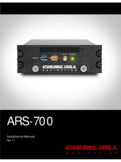
3 Technical SpecificationsAppendix A401 Table A-18 Analog Expansion Modules Output SpecificationsGeneral6ES7 232-- 0HB22-- 0XA0 6ES7 235-- 0KD22-- 0XA0 Isolation (field to logic)NoneNoneSignal rangeVoltage outputCurrent output 10 V0 to 20 mA 10 V0 to 20 mA Resolution, full-scaleVoltageCurrent12 bits plus sign bit11 bits11 bits plus sign bit11 bitsData word formatVoltageCurrent--32000 to +320000 to +32000--32000 to +320000 to +32000 AccuracyWorst case, 0 to 55 CVoltage outputCurrent outputTypical, 25 CVoltage outputCurrent output 2% of full-scale 2% of full-scale of full-scale of full-scale 2% of full-scale 2% of full-scale of full-scale of full-scaleSetting timeVoltage outputCurrent output100 S2 mS 100 S2 mS Maximum driveVoltage outputCurrent output5000 minimum500 maximum5000 minimum500 maximum24 VDC supply voltage to VDC (Class 2, Limited Power, or sensor power fromPLC)S7-200 Programmable Controller System Manual402M4--20mA--0--20mAEM 231 Analog Input,4 Inputs(6ES7 231--0HC22--0XA0)EM 232 Analog Output,2 Outputs (6ES7 232--0HB22--0XA0)EM 235 Analog Combination4 Inputs/1 Output(6ES7 235--0KD22--0XA0)
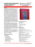
4 RA A+ A-- RB B+ B-- RC C+ C-- RD D+ D--M L+ +--+GainConfigurationM0 V0 I0M1 V1 I1M L+ 24 VDCP ower24 VDCP ower+24 VDCP owerI LOAD I LOAD V LOAD V LOAD L+D--MRA A+ A-- RB B+ B-- RC C+ C-- RD D++--GainConfigurationM0 OffsetV LOAD I LOAD +V0I0250 Ohms (built-in)250 Ohms (built-in)PS PS+--L+M0--20mAPS PS+--4--20mAL+M--+MCurrentUnusedVoltageC urrentUnusedVoltageFigure A-12 Wiring Diagrams for Analog Expansion ModulesTechnical SpecificationsAppendix A403 Analog LED IndicatorsThe LED indicators for the Analog Modules are shown in Table A-19 Analog LED IndicatorsLED IndicatorONOFF24 VDC Power Supply GoodNo faultsNo 24 VDC powerTipThe state of user power is also reported in Special Memory (SM) bits.
5 For more information, seeAppendix D, SMB8 to SMB21 I/O module ID and Error CalibrationThe calibration adjustments affect the instrumentation amplifier stage that follows the analogmultiplexer (see the Input Block Diagram for the EM 231 in Figure A-15 and EM 235 in FigureA-16). Therefore, calibration affects all user input channels. Even after calibration, variations in thecomponent values of each input circuit preceding the analogmultiplexer will cause slightdifferences in the readings between channels connected to the same input meet the Specifications , you should enable Analog input filters for all inputs of the 64 or more samples to calculate the average calibrate the input, use the following off the power to the module .
6 Select the desired input on the power to the CPU and module . Allow the module to stabilize for 15 a transmitter, a voltage source, or a current source, apply a zero value signal to oneof the input the value reported to the CPU by the appropriate the OFFSET potentiometer until the reading is zero, or the desired digital data a full-scale value signal to one of the input terminals. Read the value reported tothe the GAIN potentiometer until the reading is 32000,or the desired digital data OFFSET and GAIN calibration as and Configuration Location for EM 231 and EM 235 Figure A-13 shows the calibration potentiometer and configuration DIP switches located on theright of the bottom terminal block of the Programmable Controller System Manual404 Fixed Terminal BlockGainConfigurationOffset On Off On OffFixed Terminal BlockGainConfigurationEM 231EM 235 Figure A-13 Calibration Potentiometer and Configuration DIP Switch Location for the EM 231 and EM 235 Configuration for EM 231 Table A-20 shows how to configure the EM 231 module using the configuration DIP 1, 2, and 3 select the Analog input range.
7 All inputsare set to the same Analog inputrange. In this table, ON is closed, and OFF is open. The switchsettings are read only when thepower is turned A-20EM 231 Configuration Switch Table to Select Analog Input RangeUnipolarFullScaleInputResolutionSW1 SW2SW3 Full-Scale InputResolutionOFFON0 to 10 V mVONONOFF0 to 5 V mVONONOFF0 to 20 mA 5 ABipolarFullScaleInputResolutionSW1SW2SW 3 Full-Scale InputResolutionOFFOFFON 5 V mVOFFONOFF mVTechnical SpecificationsAppendix A405 Configuration for EM 235 Table A-21 shows how to configure the EM 235 module using the configuration DIP 1 through 6 select the Analog input range and resolution. All inputs are set to the sameanalog input range and format.
8 Table A-21 shows how to selectfor unipolar/bipolar (switch 6), gain(switches 4 and 5), and attenuation (switches 1, 2, and 3). Inthese tables, ON is closed, and OFFis open. The switch settings are read only when the power is turned A-21EM 235 Configuration Switch Table to Select Analog Range and ResolutionUnipolarFullScaleInputResoluti onSW1SW2SW3SW4SW5SW6 Full-Scale InputResolutionONOFFOFFONOFFON0 to 50 mV "VOFFONOFFONOFFON0 to 100 mV 25"VONOFFOFFOFFONON0 to 500 mV 125"VOFFONOFFOFFONON0 to 1 V 250"VONOFFOFFOFFOFFON0 to 5 V mVONOFFOFFOFFOFFON0 to 20 mA 5"AOFFONOFFOFFOFFON0 to 10 V mVBipolarFullScaleInputResolutionSW1SW2S W3SW4SW5SW6 Full-Scale InputResolutionONOFFOFFONOFFOFF+25 "VOFFONOFFONOFFOFF+50 mV25"VOFFOFFONONOFFOFF+100 mV50"VONOFFOFFOFFONOFF+250 mV125"VOFFONOFFOFFONOFF+500 mV250"VOFFOFFONOFFONOFF+1 V
9 500"VONOFFOFFOFFOFFOFF+ mVOFFONOFFOFFOFFOFF+5 V mVOFFOFFONOFFOFFOFF+10 V5 mV S7-200 Programmable Controller System Manual406 Input Data Word Format for EM 231 and EM 235 Figure A-14 shows where the 12-bit data value is placed within the Analog input word of the XX0000214 Data value 12 Bits Unipolar data153 MSBLSBAIW XX00 00 Data value 12 Bits Bipolar data40 Figure A-14 Input Data Word Format for EM 231 and EM 235 TipThe 12 bits of the Analog -to-digital converter (ADC) readings are left-justified in the data wordformat. The MSB is the sign bit: zero indicates a positive data word the unipolar format, the three trailing zeros cause the data word to change by a count of eightfor each one-count change in the ADC the bipolar format.
10 The four trailing zeros cause the dataword to change by a count of sixteenfor each one count change in the ADC Block Diagram for EM 231 and EM 235 CCA+RAA--RloopCCCB+RBB--RloopCCCC+RCC--R loopA=1A=2A=3 Input filterMUX 4 to 1 BUFFER011A/D ConverterA=4 CCCD+RDD--RloopGAIN ADJUSTI nstrumentationAMP+--EM 231 CRRRRRRRRF igure A-15 Input Block Diagram for the EM 231 Technical SpecificationsAppendix A407 REF_VOLTCCCA+RAA--RloopCCCB+RBB--RloopCC CC+RCC--RloopA=1A=2A=3 Buffer+--Input filterMUX 4 to 1 BUFFERDATA011A/D ConverterEM 235A=4 CCCD+RDD--RloopGAIN ADJUSTI nstrumentationAMP+--Offset AdjustRRRRRRRRF igure A-16 Input Block Diagram for the EM 235 Output Data Word Format for EM 232 and EM 235 Figure A-17 shows where the 12-bit data value is placed within the Analog output word of XX00 00 314 Data value 11 BitsCurrent output data format153 MSBLSBAQW XX00 00 Data value 12 BitsVoltage output data format400 Figure A-17 Output Data Word Format for EM 232 and EM 235 TipThe 12 bits of the digital-to- Analog converter (DAC) readings are left-justified in the output dataword format.