Transcription of Analysis of Bonding Strength of Ultrasonic Welding Process
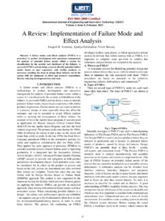
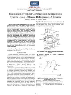
1 ISSN: 2277-3754. ISO 9001:2008 Certified International Journal of Engineering and Innovative Technology (IJEIT). volume 4, Issue 5, November 2014. Analysis of Bonding Strength of Ultrasonic Welding Process Vijay Singh pal, Pavan Agrawal Abstract: - In Ultrasonic Welding , high frequency vibrations are combined with pressure to join two materials together quickly and securely. Ultrasonic Welding can join dissimilar metals in a split second, Ultrasonic Welding eases problematic assembly and this cost effective technique may be key to mass producing fuel efficient. In this work effect of various parameters on weld Strength have been studied. Welding of .5. mm aluminium plates were successfully welded by 20 kHz Ultrasonic Welding system. One dimensional vibration system for Ultrasonic lap spot Welding of metal plate of aluminium Fig 1 Ultrasonic metal Welding have studied.
2 The relationships between weld Strength and the variables of weld energy, duration of weld cycle, have studied Experiment was carried out to determine the mechanism of III. PARAMETER CONTROL. aluminium- aluminium plate Bonding . These experiment, 1. Welding pressure or clamping pressure including effect of amplitude and pat tern of bond formation. 2. Welding voltage Experiment was carried to find out the optimum parameter for 3. Welding current maximum Strength . 4. Ultrasonic frequency 5. Welding time 6. Welding energy I. INTRODUCTION 7. Constant amplitude Ultrasonic Welding is an industrial technique whereby 8. Weld location two pieces of plastic or metal are joined together seamlessly through high-frequency acoustic vibrations. IV. Welding IN THE ENERGY MODE.
3 One component to be welded is placed upon a fixed anvil, Welding in energy mode, with a constant energy with the second component being placed on top. An setting, is known from Ultrasonic plastics Welding and can extension ("horn") connected to a transducer is lowered also be used for Ultrasonic metal Welding . To achieve a down onto the top component, and a very rapid (~20,000 constant quality the Welding time is automatically Hz), low-amplitude acoustic vibration is applied to a adjusted. Although this type of quality control is good small Welding zone. The acoustic energy is converted into with Ultrasonic plastics Welding , the approach has to be heat energy by friction, and the parts are welded together more carefully applied when it comes to Ultrasonic metal in less than a second.
4 Welding . II. Ultrasonic METALS Welding V. Welding IN ENERGY MODE. The system that is used to scrub the pieces together Energy: 2000 ws Weld location: at middle of lap consists of four major components. The first of these is Amplitude: 70%. the anvil. This is simply a piece of the machine, usually Pmax =300 w with a replaceable head, that holds one of the components Sr. WELD TIME %Pmax T2*% Strength (WEIGHT). still while the other is rubbed against it. The "business NO. IN Pmax IN KG. end" of the Ultrasonic system consists of three major SECONDS(T2). parts. The first of these is the Ultrasonic transducer. This component takes an electrical signal from a power supply that is providing a 20 khz AC signal and converts it to a 1 55 mechanical motion at the same frequency as shown in fig 1.
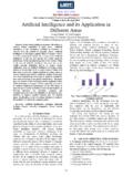
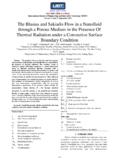
5 The vibration that results is at a frequency that is 2 53 appreciably above the range of human hearing, hence the 3 40 9. name Ultrasonic . There is a power supply which elevates the frequency of the electrical current from the grid, then 4 62 the transducer that transforms electrical into mechanical 5 55 10. energy, then a booster that modifies the shape and magnitude of vibrations an finally the horn that vibrates 6 62 the material to be welded, while it is clamped unto the Table 1 - weld time and Strength in energy mode stationary anvil. 181. ISSN: 2277-3754. ISO 9001:2008 Certified International Journal of Engineering and Innovative Technology (IJEIT). volume 4, Issue 5, November 2014. Welding IN TIME MODE. TIME: s Weld location: at end edge of lap Amplitude: 70%.
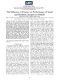
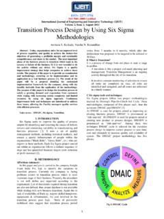
6 Pmax =300w Piece Weld %Pmax %Pmax*weld Strength (weight). no energy. energy. In Kg In WS. Fig 2. Relation between weld time and Strength in energy 1 670 45 30150 mode 2 680 47 31960 3 720 46 33120 VI. Welding IN THE TIME MODE 4 52 39308 9. This is the most suitable mode for Ultrasonic metals 5 881 45 39645 9. Welding . Welding energy and rate of compression are 6 816 50 40800 9. variable, but we only consider the variation in energy 7 850 50 42500 because rate of compression does minor effect on weld 8 964 51 49164 10. Strength subject to the deviations of the work piece. They Table 3- weld energy and Strength at 70% amplitude at end should, however, stay within acceptable limits. The Welding Process ends automatically as soon as the nominal time value is achieved.
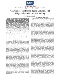
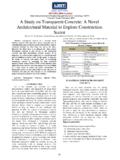
7 The Welding time is defined as the duration of Ultrasonic and can be both a constant parameter and a variable parameter adjusted with the help of quality control devices for an optimum weld. Depending on the application the Welding time can be between and approximately 4 seconds. Fig 4. Relation between weld energy and Strength at 70%. Welding IN TIME MODE amplitude at end TIME: s Weld location: at middle of lap VII. COMPARISON BETWEEN Welding AT. Amplitude: 70% THE MIDDLE OF THE LAP AND AT THE EDGE. Pmax =300 w OF THE LAP. Piece Weld %Pmax %Pmax*weld Strength (weight) Front view no energy. Energy. In Kg In WS. 1 912 33 30096 3. 2 1043 39 40677 4. 3 1281 64 81984 10. 4 1450 57 82661 10. 5 1451 60 87060 10. 6 71 95556 7 1655 60 99300 11. 8 1845 55 101475 11.
8 9 1708 68 116144 Top view Table 2 weld energy and Strength at 70% amplitude Fig 5 Welding at middle of lap Front view Top view Fig. 3. Relation between weld energy and Strength at 70%. Fig 6. Welding at end edge of lap amplitude 182. ISSN: 2277-3754. ISO 9001:2008 Certified International Journal of Engineering and Innovative Technology (IJEIT). volume 4, Issue 5, November 2014. TIME: s In this work, the controllable factors taken are Voltage Amplitude: 70% (V), Current (I) and pressure (P). Since they affect Pmax =300w Strength and Welding operation and these factors are Sr. At the middle of the lap At the edge of the lap controllable in the Ultrasonic Welding Process , they are no considered as a controllable factor. Energy (ws) Strength Energy Strength (Kg) (ws) (Kg) B.
9 Analysis of means and response graph for 1 912 3 670 Strength 2 1043 4 680 Analysis of means The Analysis of each controllable factor is studied and the 3 1281 10 720 main effect of the same is obtained in table. Main effect 4 1450 10 9 of each factor at individual level at low, medium and 5 1451 10 881 9 high level is equal to the mean of Strength of all 6 816 9 experiments with the factor at individual level. 7 1655 11 850 (a) The main effect of voltage on Strength at various level calculated as follows 8 1845 11 964 10. L = ( + +9)/3 = Kg Table 4. Comparison between Welding at the middle of the M = ( + +8)/3 = Kg lap and at the edge of the lap H = ( + + )/3 = Kg Table 4 shows that in case of Welding at the edge of the (b)The main effect of current on Strength at various level lap the Bonding Strength is much more compare to calculated as follows Welding at the middle of the lap.
10 It also consumes less L = ( + + )/3 = Kg energy and gives better Strength . Because in case of M = ( + + )/3 = Kg Welding at the edge of the lap the surrounding is mainly H = (9+8+ )/3 = Kg air Which have low thermal conductivity compare to (c) The main effect of pressure on Strength at various aluminum in case of Welding at the middle of the lap. level calculated as follows Because of high thermal conductivity of aluminum, the L = ( + + )/3 = Kg heat losses is more in case of Welding at the middle of M = ( +8+ )/3 = Kg the lap compare to in case of Welding at the edge of the H = (9+ + )/3 = Kg lap. So the Welding at the edge is prefer than Welding at the middle. Symbols Controllable factors Strength (Kg). VIII. EXPERIMENTATION AND DATA Low Medium High COLLECTION V Voltage 7 Symbols Process Levels I Current parameter Low Medium High P Pressure V Voltage 230 340 450.