Transcription of ANALYSIS OF COULOMB AND JOHNSEN-RAHBEK …
1 ANALYSIS OF COULOMB AND JOHNSEN-RAHBEK electrostatic CHUCK performance FOR EUV LITHOGRAPHY Michael R. Sogard1, Andrew R. Mikkelson2, Madhura Nataraju3, Kevin T. Turner2, and Roxann L. Engelstad2 1 Nikon Research Corporation of America Belmont, CA 94002 2 Computational Mechanics Center University of Wisconsin Madison Madison, WI 53706- 3 Intel Corporation Santa Clara, CA 95054 INTRODUCTION The imaging system in extreme ultraviolet lithography (EUVL) incorporates a reflective mask that is subjected to non-telecentric illumination during exposure. As a result, any nonflatness ( , variation of the height) of the pattern surface results in image placement errors on the device wafer. For this reason, it is imperative that the frontside and backside of the reticle, as well as the electrostatic chuck (ESC), be exceptionally flat to meet the critical dimension control and overlay budget requirements.
2 The EUVL Mask Standard, SEMI P37, specifies that the substrate surface nonflatness not exceed 100 nm peak-to-valley (p-v) [1]. SEMI P40, the EUVL Mask Chucking Standard, requires the chucking surface nonflatness to be less than 50 nm p-v [2]. Consequently, EUVL depends upon the capability of an ESC to reduce the final mask nonflatness; the successful implementation of EUVL requires this flattening capability be characterized, predicted, and well-understood. An ESC clamps a substrate to a dielectric chuck surface by electrostatic force. Two types of electrostatic chucks are the COULOMB and JOHNSEN-RAHBEK (J-R) [3,4]. These are distinguished by the characteristics of their dielectrics and the resulting mechanism of clamping force generation.
3 The COULOMB chuck functions like a conventional dielectric capacitor. The J-R dielectric has a large but finite resistance, so a current flows through it and the substrate when the surfaces are in contact and voltage is applied. Charge accumulates at the interface between substrate and dielectric. Since the thickness of the interface region is related to surface roughness, the charge separation is typically quite small, and strong electrostatic forces can be generated. COULOMB STYLE CHUCK For a monopolar COULOMB chuck, the electrostatic pressure, P, is given by: ()2222ooDVKPtK =+, (1) where Vo is the applied voltage, K is the relative permittivity of the dielectric, o is the permittivity of free space ( 10-12 F/m), tD is the dielectric thickness, and is the total gap between the backside of the mask and the dielectric surface.
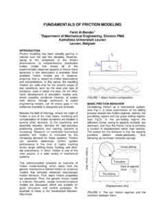
4 For a given magnitude of applied voltage, the pressure generated by a monopolar chuck is four times larger than that from a bipolar chuck. Only monopolar chucks are examined in this paper. A characteristic of the COULOMB chuck is that clamping pressure exists everywhere between the reticle and chuck. Typical values for tD in a COULOMB chuck are 100-200 m and the K term in the denominator of the pressure equation is often an order of magnitude smaller than tD. Thus, the clamping force is virtually unaffected in the presence of non-flat substrates or entrapped particles (considering relatively small gaps), as illustrated in Fig. 1. JOHNSEN-RAHBEK STYLE CHUCK Details of the clamping characteristics of a J-R chuck are illustrated in Fig. 2(a). When voltage is applied, charge accumulates along the rough chuck-substrate interface, or contact layer.
5 This layer has a thickness tCL which is related to surface roughness, as illustrated in the figure. The properties of the chuck also depend on the resistances of the bulk dielectric (RV) and the contact layer (RCL). In addition to the attractive force generated in the contact layer, a conventional COULOMB chuck force is also generated between the substrate and the chuck electrode. Chuck+-VoDielectric Material (K o)tDReticle = air gapChuck+-VoDielectric Material (K o)tDReticle = air gap (a) (b) FIGURE 1. (a) Characteristics of a COULOMB chuck and (b) corresponding pressure distribution with an entrapped particle. While the details of the accumulated charge in the contact layer are quite complicated, a phenomenological model of the J-R chuck force mechanism can be created by treating the contact layer as a small air gap capacitor, of thickness tCL.
6 The amount of charge deposited at the contact layer (or equivalently the voltage drop) can be related to the relative values of RV and RCL, which function as a resistive divider. This results in the following expression for the clamping pressure, P: JRCOULPPP+= (2) where, ()22002 ++=CLDCOULtKtKVP (3) and ()(){}220012 +=VCLCLVCLJRRRtRRVP (4) The parameter is an empirical factor representing the effect of a nonuniform charge distribution on the interface, and is now the physical gap between the reticle and dielectric layer. In practice RV and RCL can be measured; tCL can then be obtained from a measurement of pressure at a given voltage. The first term in the expression arises from the conventional COULOMB force between the chuck electrode and the substrate. The second term arises from the J-R effect.
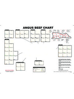
7 Typically tD >> tCL, so the COULOMB term is negligible compared to the J-R term. The empirical factor represents the effect of the non-uniform distribution of charge on the interface surfaces. Here a value of was assumed [5]. The J-R force depends on electrical contact between the chuck and substrate. This leads to distinctly different behavior from that of the COULOMB chuck when nonflat substrates or particles are present, as illustrated in Fig. 2(b). No clamping force is generated in the non-contacting regions. This brings into question the effectiveness of the J-R chuck for high flatness requirement applications, and is a major motivation for the present study. ChuckReticle+-VoRVtCLRCL+++++++Charge Accumulation----------++++++-----ChuckRe ticle+-VoRVRVtCLRCL+++++++Charge Accumulation----------++++++----- (a) No J-R force here because no physical contactNo J-R force here because no physical contact (b) FIGURE 2.
8 (a) Characteristics of a J-R chuck and (b) corresponding pressure distribution with an entrapped particle. Finite element (FE) analyses have been used to investigate the J-R performance for nonflat substrates. However, the contact requirement for J-R force generation causes a problem, because of the finite mesh of the model. Therefore, for computational convenience a finite range is assumed for the J-R force. The finite range is introduced into Eq. (4) by redefining the constant as a gap dependent function, which decreases from at zero gap to zero at a gap of 30 nm. While this finite range is introduced to facilitate convergence within the FE model, short range forces, such as van der Waals ( 1 / gap3) and Casimir ( 1 / gap4) exist over a comparable distance [6] and would be included in a more complete theory.
9 FINITE ELEMENT MODEL In order to predict the clamping ability of COULOMB and J-R electrostatic chucks , full three-dimensional FE models were developed. Parameters were chosen to be representative for each style of chuck and the initial nonflatness of both surfaces of the reticle and of the pin surface of the chuck were based on interferometric measurements of actual chucks and reticles to provide a realistic and impartial comparison [7]. The pin chuck was modeled to have a 12 12 array of square pins, each having a side length of mm and a height of 10 m. The pin pitch was mm and the coverage was 4%. The pin region was 142 mm2 corresponding to the reticle quality area. The chuck was assumed to have an elastic modulus of 380 GPa and a Poisson s ratio of , which is typical for ceramic materials used in electrostatic chucks .
10 A total thickness of mm was used for the body of the chuck, which included a 150 m thick dielectric for the COULOMB chuck and mm thick dielectric for the J-R chuck. Separate models were developed for each style of chuck and each model included the local gap-dependent pressure. All gravitational effects were ignored, and the coefficient of friction was assumed to be The simulations were then used to predict the final flatness of the reticle patterned and backside surfaces, the final bow (or flatness) of the chuck, the final gap between the reticle and chuck, and also the pressure distribution on the backside surface of the reticle or the pressure distribution on the pins. For each model it was assumed that the relative dielectric constant was 10. The model of the COULOMB chuck utilized an applied voltage range of 365 to 895 V, which corresponds to an average pressure (with complete chucking) of to kPa.