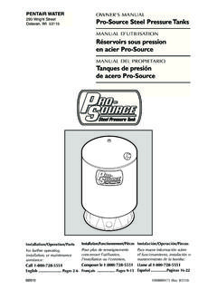
Transcription of and 200M/B CENTRIFUGAL PUMPS - files.pentairliterature.com
1 NOTE! To the installer: Please make sure you provide this manual to the owner of the equip ment or to the responsible party who maintains the AND SERVICE MANUALCENTRI-THRIFT CENTRIFUGAL PUMPSENGLISH: PAGES 2-8 Installation and Service ManualNOTE! To the installer: Please make sure you provide this manual to the owner of the equipment or to the responsible party who maintains the # 13800A085 | 2018 Pentair plc | 8/24/18 Models 125M/B, 150M/B and 200M/BMYERS2 Important safety instructions! Read carefully before Proposition 65 Warning: This product and related accessories contain chemicals known to the State of California to cause cancer, birth defects or other reproductive Drinking Water Act: This product is to be used exclusively for non-potable water services. This product is not anticipated to be used for human consumption so is not designed for the low lead levels stated in the Safe Drinking Water Act.
2 It is illegal to use this product for potable water applications for human consumption, such as drinking water, oral hygiene, hand washing, food preparation and to follow these instructions and comply with all codes may cause serious bodily injury and/or property installing or servicing your pump, be certain the pump power source is turned off and installation and electrical wiring must adhere to state and local codes. Check with appropriate community agencies or contact your local electrical and pump professionals for must be connected to a separate electrical circuit directly from the entrance box. There must be an appropriately sized fuse or circuit breaker in this line. Tying into existing circuits may cause circuit overloading, blown fuses, tripped circuit breakers or a burned-up not connect pump to a power supply until the pump is grounded.
3 For maximum safety, a ground fault interrupter should be used. Failure to ground this unit properly may result in severe electrical risk of electric shock during operation of this pump requires acceptable grounding. If the means of connection to the supply-connection box is other than grounded metal conduit, ground the pump back to the service by connecting a copper conductor, at least the size of the circuit conductors supplying the pump, to the grounding screw provided within the wiring pump is provided with a means for grounding. To reduce the risk of electric shock from contact with adjacent metal parts, bond supply box to the pump-motor-grounding means and to all metal parts accessible including metal discharge pipes, by means of a clamp, a weld or both if necessary, secured to the equipment-grounding voltage and phase of the power supply must match the voltage and phase of the not use an extension cord.
4 Above ground joints must be made in an approved junction operate a pump with a frayed or brittle power cord, and always protect it from sharp objects, hot surfaces, oil and chemicals. Avoid kinking the service a motor or power cord with wet hands or while standing in or near water or damp not use this pump in or near a swimming three phase units must be wired by a qualified electrician, using an approved starter box and switching phase motors are equipped with automatic resetting thermal protectors. The motor may restart unexpectedly, causing the leads to energize or pump to turn on. Three phase motors should be protected by proper thermal and amperage protection. (Check local codes.)Check for nicks in the wire and pump insulation by using an ohmmeter and checking resistance to ground after installing the pump. If in doubt on the proper procedure, check with a qualified not pump gasoline, chemicals, corrosives or flammable liquids; they could ignite, explode or damage the pump, causing injury and voiding the work on the pump or system without relieving the internal not pump water above 120 exceed the pressure rating of any system must line up and not be forced into position by unions.
5 Piping should be independently supported near the pump so that no strain will be placed on the pump casing. Where any noise is objectionable, pump should be insulated from the piping with rubber connections. Always keep pipe size as large as possible and use a minimum of fittings to reduce friction PipingSuction pipe should be direct and as short as possible. It should be at least one size larger than suction inlet tapping and should have a minimum of elbows and fittings. The piping should be laid out so that it slopes upward to pump without dips or high points to eliminate air pockets. The highest point in the suction piping should be the pump inlet except where liquid flows to the pump inlet under pressure. A foot valve must be used to keep pump primed. Where liquid flows to the pump, it may be desirable to use a check valve in the suction line or discharge line to keep pump prevent air from being drawn into suction pipe due to a suction whirlpool, the foot valve should be submerged at least three feet below the low water level.
6 The suction pipe must be tight and free of air PipingDischarge piping should never be smaller than pump tapping and should preferably be one size larger. A gate valve should always be installed in discharge line to serve as a shut-off for throttling if capacity is not correct. To protect the pump and foot valve from water hammer and to prevent back flow, a check valve should be installed in the discharge line between the pump and gate ConnectionsBe sure motor wiring is connected for voltage being used. 3 Unit should be connected to a separate circuit, direct from main switch. A fused disconnect switch or circuit breaker must be used in this circuit. Wire of sufficient size should be used to keep voltage drop to a maximum of 5%. All motors, unless provided with built-in overload protection, must be protected with an overload switch, either manual or magnetic.
7 Three phase motors require overload protection. Single phase motors are equipped with built-in overload protection. Never install a pump without proper overload protection. A flexible metallic conduit should be used to protect the motor pump must be primed before starting. The pump casing and suction piping must be filled with water before starting motor. Remove vent plug in top of casing while pouring in priming water. A hand pump or ejector can be used for priming when desired. Use care to remove all air before starting motor. If pump does not start immediately, stop and the discharge valve when starting the pump as it puts less starting load on the motor. When the pump is up to operating speed, open the discharge valve to obtain desired capacity or pressure. Do not allow the pump to run for long periods with the discharge valve tightly closed.
8 This will create superheated water, which could damage the seal and shorten the life of the motor. This superheated water could also cause severe burns. Always use a pressure relief valve, set below the rating of the tank system. RotationThe pump must run in direction of arrow on pump case. All single phase motors are single rotation. Three phase motors may run either direction. If rotation is wrong when first starting motor, interchange any two line leads to change stopping pump, close the discharge valve. This will prevent water hammer and is especially important on high head should be taken to prevent the pump from freezing during cold weather. Drain the pump casing when not in operation. Drain by removing the pipe plug in the bottom of the SealCentrifugal PUMPS are fitted with rotary seal. This seal is recommended for water free from abrasives.
9 If liquid contains abrasives, the CENTRIFUGAL pump should not be motor bearings in accordance with motor manufacturer s seal ball bearings are used on 125B, 150B and 200B bearing bracket units. Proper amount of grease has been provided in the bracket cavity between the bearings. This should be sufficient grease for 4,000 hours of operation. After 4,000 hours of operation the old grease should be cleaned out and new grease added. Use only best grade ball bearing greasesDISASSEMBLY INSTRUCTIONSOpen the power supply switch contacts and remove fuses. Disconnect the electrical wiring from the motor. Then drain pump case by removing drain the bolts securing volute case to pump bracket, and pry components apart. Then remove replace both rotating assembly and stationary ceramic seat. Do not use old stationary seat with new rotating seal assembly.
10 Pry out rotating assembly of shaft seal and remove ceramic ring from housing. A new shaft seal should always be used when rebuilding a pump. All pump parts should be cleaned thoroughly before being four bolts holding bracket to motor and remove motor. Then remove set screw in stub shaft coupling to disconnect motor pump INSTRUCTIONSP lace rubber deflector over motor shaft, slide shaft extension into position and tighten set screws. Assemble motor and shaft onto seal seat in position by using finger pressure to press firmly and squarely until it bottoms. The use of light oil on the rubber element will facilitate assembly. Care must be taken to keep oil, grease and dirt off face areas of seal. Be sure the seal faces are not damaged during assembly or the seal will leak during dimension from face of ceramic seat to shaft shoulder.