Transcription of AND DUNCAN C. WYLLIE ROCK SLOPE STABILITY ANALYSIS
1 KChapter 15 NORMAN I. NoiuusH AND DUNCAN C. WYLLIE ROCK SLOPE STABILITY ANALYSIS 1. INTRODUC11ON Except for the rare case of a completely un-fractured rock unit, the majority of rock masses can be considered as assemblages of intact rock blocks delineated in three dimensions by a system of discontinuities. These discontinuities can occur as unique randomly oriented features or as repeating members of a discontinuity set. This system of structural discontinuities is usually re-ferred to as the structural fabric of the rock mass and can consist of bedding surfaces, joints, folia-tion, or any other natural break in the rock.
2 In most cases, engineering properties of fractured rock masses, such as strength, permeability, and de-formability, are more dependent on the nature of the structural fabric than on the properties of the intact rock. For this reason, practitioners in the field of rock mechanics have developed the follow-ing parameters to characterize the nature of the discontinuities that make up the structural fabric: Orientation: The orientation of a discontinuity is best defined by two angular parameters: dip and dip direction. Persistence: Persistence refers to the continuity or areal extent of a discontinuity and is particu-larly important because it defines the potential volume of the failure mass.
3 Persistence is diffi-cult to quantify; the only reliable means is map-ping of bedrock exposures. Spacing: The distance between two discontinu- ities of the same set measured normal to the dis-continuity surfaces is called spacing. Together, persistence and spacing of discontinuities define the size of blocks. They also influence the dila-tancy of the rock mass during shear displace-ment and determine the extent to. which the mechanical properties of the intact rock will govern the behavior of the rock mass. Surface properties: The shape and roughness of the discontinuity constitute its surface proper-ties, which have a direct effect on shear strength.
4 Infillings:Minerals or other materials that occur between the intact rock walls of disconti-nuities are termed infillings. Their presence can affect the permeability, and shear strength of a discontinuity. Secondary minerals, such as cal-cite or quartz, may provide significant cohesion along discontinuities. However, these thin in-fillings are susceptible to damage by blasting, re-sulting in total loss of cohesion. For all but very weak rock materials, the ANALYSIS of rock SLOPE STABILITY is fundamentally a two-part process. The first step is to analyze the structural fabric of the site to determine if the orientation of the discontinuities could result in instability of the SLOPE under consideration.
5 This determination is usually accomplished by means of stereographic ANALYSIS of the structural fabric and is often referred to as kinematic ANALYSIS (Piteau and Peckover 1978). Once it has been determined that a kinematically possible failure mode is present, the second step re- 392 Landslides: Investigation and Mitigation quires a limit-equilibrium STABILITY ANALYSIS to com-pare the forces resisting failure with the forces causing failure. The ratio between these two sets of forces is termed the factor of safety, FS. For very weak rock where the intact material strength is of the same magnitude as the induced stresses, the structural geology may not control STABILITY , and classical soil mechanics principles for SLOPE STABILITY ANALYSIS apply.
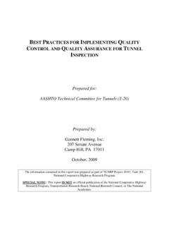
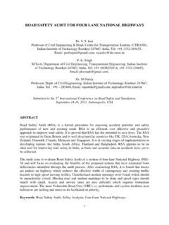
6 These procedures are discussed in Chapter 13. 2. TYPES OF ROCK SLOPE FAILURES As shown in Figure 15-1, most rock SLOPE failures can be classified into one of four categories depend-ing on the type and degree of structural control: Planar failures are governed by a single disconti-nuity surface dipping out of a SLOPE face [Figure 15-1(a)], Wedge failures involve a failure mass defined by two discontinuities with a line of intersection that is inclined out of the SLOPE face [Figure 15-1(b)], Toppling failures involve slabs or columns of rock defined by discontinuities that dip steeply into the SLOPE face [Figure 15-1(c)], and Circular failures occur in rock masses that are either highly fractured or composed of material with low intact strength [Figure 15-1(d)].
7 Recognition of these four categories of failures is essential to the application of appropriate analyt-ical methods. 3. STEREOGRAPHIC ANALYSIS OF STRUCTURAL FABRIC From a rock SLOPE design perspective, the most important characteristic of a discontinuity is its (a) Wedge failure on two Planar failure in rock in which a intersecting discontinuities with discontinuity 'daylights" the a line of intersection which SLOPE face "daylights" the SLOPE FIGURE 15-1 (facing pages) Types of rock SLOPE failures: planar failure, wedqe failure, toppling failure, circular failure (diagrams modified from Hoek and Bray 1981).
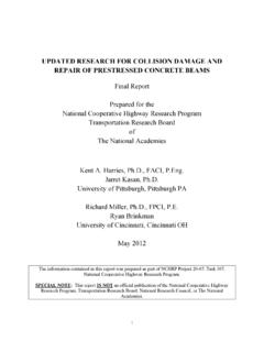
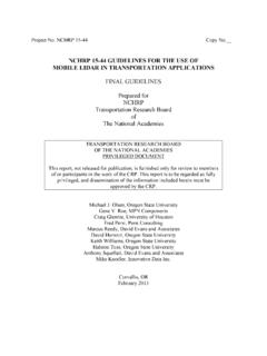
8 NORRIS!-! AND WYLLIE - I Rock SLOPE STABILITY ANALYSIS 393 orientation, which is best defined by two parame-ters: dip and dip direction [Figure 15-2(a)]. The dip angle refers to the inclination of the plane below the horizontal and thus ranges from 0 to 90 de-grees. The dip direction of the plane is the azimuth at which the maximum dip is measured and ranges from 0 to 360 degrees. The dip direction differs from the strike direction by 90 degrees and is the preferred parameter to avoid ambiguity as to the di-rection of dip. These values are determined by compass measurements on rock outcrops (Chapter 9), oriented drilling techniques, or interpretation of geologic structural trends (Chapter 8).
9 Interpretation of these geologic structural data requires the use of stereographic projections that allow the three-dimensional orientation data to he represented and analyzed in two dimensions. The most commonly used projections are the equal-area net and the polar net, replications of which are shown in Appendix A. The rock SLOPE practitioner is referred to the work by Hock and Bray (1981), Hock and Brown (1980), and Goodman (1976) for in-depth treat-ment of the principles of stereographic ANALYSIS . A detailed presentation of the procedures for plot-ting, analyzing, and interpreting data on stereo-graphic projections is beyond the scope of this report; however, these techniques are essential to rock SLOPE design and to the following discussion.
10 Stereographic presentations remove one dimen-sion from consideration so that planes can be rep-resented by lines and lines represented by points. Stereographic analyses consider only angular re-lationships between lines, planes, and lines and planes. These analyses do not in any way represent the position or size of the feature. The fundamental concept of stereographic pro-jections consists of a reference sphere that has a fixed orientation of its axis relative to the north and of its equatorial plane to the horizontal [Figure (c) Toppling failure in hard rock with slabs or columns defined by discontinuities that dip steeply into the SLOPE Circular failure in overburden soil, waste rock or heavily fractured rock with no identifiable structural pattern 394 Landslides: Investigation and Mitigation FIGURE 15-2 Concepts for stereographic representation of linear and planar features (modified from Hoek and Bray 1981).]