Transcription of Anti-lock Brake System (ABS) - ken-gilbert.com
1 Anti-lock Brake System (ABS) ABS 1. Anti-lock Brake System (ABS) A: FEATURE 0 The type ABS used in the lmpreza has a hydraulic control unit, an ABS control module, a valve relay and a motor relay integrated into a single unit (called ABSCM & H/U ) for circuit sim- plicity and reduced weight. 0 The ABS electrically controls the Brake fluid pressure to each wheel to prevent the wheel from locking during braking on slippery road surfaces, thereby enabling the driver to maintain the directional control. 0 If the ABS becomes inoperative, a fail-safe System is activated to ensure same level of braking performance as with a conventional Brake System . In that case, the warning light comes on to indi- cate that the ABS is malfunctioning. 0 The ABS is a 4-sensor, 4-channel System ; the front wheel System is an independent control de- sign* , while the rear wheel System is a select-low control design*2. *I : A System which controls the front wheel brakes individually.
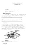
2 *2: A System which applies the same fluid pressure to both the rear wheels if either wheel starts to lock. The pressure is determined based on the lower of the frictional coefficients of both wheels. (1) ABS control module and hydraulic (5) G sensor (2) Proportioning valve (6) ABS warning light (3) Diagnosis connector (7) Tone wheel (4) Data link connector (8) ABS sensor control unit (ABSCM 8, H/U) (for SUBARU select monitor) ABS-2 NF0197 (9) Wheel cylinder (1 0) Automatic transmission control module (1 1 ) Brake switch (1 2) Master cylinder Anti-lock Brake System (ABS) ABS B: FUNCTIONS OF SENSORS AND ACTUATORS Name 4BS control module and iydraulic control unit :ABSCM & H/U) ABSCM section HIU section Valve relay section Motor relay section ABS sensors (wheel speed sensors) Tone wheels S sensor Stop light switch ABS warning light Automatic transmission control module Function 0 It determines the conditions of the wheels and the vehicle body from the wheel speed data and controls the hydraulic unit depending on the re- sult.
3 0 When the ABS is active, the ABSCM provides the automatic transmis- sion control module with control signals which are used by the module for cooperative control of the vehicle with the ABSCM. 0 Whenever the ignition switch is placed at ON, the module performs a self diagnosis sequence. If anything wrong is detected, the module cuts off the System . 0 It communicates with the SUBARU select monitor. 0 When the ABS is active, the H/U changes fluid passages to the wheel cylin- ders in response to commands from the ABSCM. 0 It constitutes the Brake fluid passage from the master cylinder to the wheel cylinders together with the piping. It serves as a power switch for the solenoid valves and motor relay coil. It operates in response to a command from the ABSCM. It serves as a power switch for the pump motor. It operates in response to a command from the ABSCM. They detect the wheel speed in terms of a change in the density of the magnetic flux passing through them and convert it into an electrical signal.
4 The electrical signal is sent to the ABSCM. They give a change in the magnetic flux density by the teeth around them- selves to let the ABS sensors generate electrical signals. It detects a change in acceleration in the longitudinal direction of the ve- hicle and outputs it to the ABSCM as a voltage signal. It provides information on whether the Brake pedal is depressed or not to the ABSCM. The ABSCM uses it to determine ABS operation. It alerts the driver to an ABS fault. When the diagnosis connector and diag- nosis terminal are connected, the light flashes to indicate a trouble code stored in the ABSCM. It provides gear controls (fixing the speed at 3rd or changing power trans- mission to front and rear wheels) in response to control signals from the ABSCM. ABS-3 Anti-lock Brake System (ABS) ABS EATERY 0- -L I - - I IGN ABS control module and hydraulic control unit ABS control module section Valve relay Motor relay Motor Front left inlet solenoid valve Front left outlet solenoid valve Front right inlet solenoid valve II (9) Front right outlet solenoid valve Rear left inlet solenoid valve Rear left outlet solenoid valve Rear right inlet solenoid valve Rear right outlet solenoid valve Automatic transmission control module Diagnosis connector Data link connector (23) (24) ABS warning light Stop light switch Stop light G sensor Front left ABS sensor Front right ABS sensor Rear left ABS sensor Rear right ABS sensor NF0198 ABS-4 Anti-lock Brake System (ABS) ABS C: PRINCIPLE OF ABS CONTROL When the Brake pedal is depressed during driving, the wheel speed decreases and the vehicle speed does as well.
5 The decrease in the vehicle speed, however, is not always proportional to the decrease in the wheel speed. The non-correspondence between the wheel speed and vehicle speed is called slip and the magnitude of the slip is expressed by the slip ratio which is defined as follows: Slip ratio = Vehicle speed - Wheel speedNehicle speed x 100% When the slip ratio is 0%, the vehicle speed corresponds exactly to the wheel speed; when it is loo%, the wheels are completely locking (rotating at a zero speed) while the vehicle is moving. The braking effectiveness is represented by the coefficient of friction between the tire and road surface. The larger the Coefficient, the higher the braking effectiveness. The diagram below shows the relationship between the coefficient of friction and the slip ratio for two different road surface conditions (asphalt-paved road and icy road), assuming that the same tires are used for both the conditions and the vehicles are moving forward.
6 Although the braking effectiveness (coefficient of friction) depends on the road surface condition as shown and also on the type of the tire, its peak range generally corresponds to the 8 - 30% range of the slip ratio. The ABS controls the fluid pressure to each wheel so that a coefficient of friction corresponding to this dip ratio range is maintained. Control range by ABS Asphalt-paved road Icy road -- I * loo(%) Slip ratio 0 ABS-5 NF0199 Anti-lock Brake System (ABS) ABS D: ABS SENSORS Each of the ABS sensors detects the speed of the corresponding wheel. The sensor consists of a permanent magnet, coil and tone wheel. The magnetic flux produced by the permanent magnet changes as each tooth of the tone wheel (which rotates together with the wheel) passes in front of the magnet s pole piece. The changing magnetic flux induces voltages at a frequency corre- sponding to the wheel speed. (A) (B) (A) Front (B) Rear (4) +v I / (3) \ I i -V i (1 ) Sensor body (4) Full speed (2) Pole piece (5) Low speed (3) Tone wheel (6) Permanent magnet NF0200 ABS-6 Anti-lock Brake System (ABS) ABS E: ABS CONTROL MODULE AND HYDRAULIC CONTROL UNIT (ABSCM & H/U) 0 ABS CONTROL MODULE SECTION (ABSCM) The ABSCM contains two microcontrol modules (MCMs): master and slave.
7 Both the MCMs pro- cess the same program and each MCM monitors the other s outputs. If a mismatch occurs be- tween their outputs, the ABSCM cuts off the System and activate the fail-safe function. The ABSCM can store a maximum of 3 trouble codes in an EEP ROM. If more than 3 faults have occurred, only the 3 most recent failures are stored and others are erased. Trouble codes remain stored until they are internally or externally erased. The ABSCM has a test routine (sequence control pattern) which facilitates checking of the hydrau- lic control unit. 0 ABS control Using primarily the wheel speed data from each ABS sensor and secondarily the vehicle decelera- tion rate data from the G sensor as parameters, the ABSCM generates a simulated vehicle speed when there is a risk of wheel lock-up. Using the simulated vehicle speed (called dummy vehicle speed) as a reference, the ABSCM determines the state of the wheel in terms of the tendency to- ward lock-up.
8 If the result shows that the wheels are about to lock, the ABSCM issues commands to energize or de-energize the solenoid valves and activate the motor pump of the H/U to modulate the Brake fluid pressures that act on the wheel cylinders, thereby preventing the wheels from lock- ing. The ABSCM controls the right and left front wheel fluid pressures independently and the rear wheel fluid pressures based on the wheel which is the most likely to lock (select-low control). 0 Functions available using SUBARU select monitor When the SUBARU select monitor is connected, the ABSCM allows it 0 To read out analog data 0 To read out ON/OFF data 0 To read out or erase trouble code 0 To read out data showing conditions under which a trouble code has been stored (Freeze frame data) 0 To initiate ABS sequence control pattern 0 Indication functions Under the control of the ABSCM, the ABS warning light provides the following three indication func- tion: 0 ABS fault alerting 0 Trouble code indication (by flashing in the diagnosis mode) 0 Valve ON/OFF indication (when sequence control pattern is initiated) ABS-7 Anti-lock Brake System (ABS) ABS 0 HYDRAULIC CONTROL UNIT SECTION (H/U) The H/U is a fluid pressure controller consisting of, among others, a motor, solenoid valves, a hous- ing and relays.
9 It also constitutes passage of the two diagonally split Brake circuits. 0 The pump motor drives an eccentric cam which in turn moves the plunger pump to generate hyd rau I ic pressure. 0 The housing accommodates the pump motor, solenoid valve and reservoir. It also constitutes a Brake fluid passage. 0 The plunger pump, when operated, draws the Brake fluid from the reservoir, lets the fluid in a wheel cylinder drain into the reservoir, and/or forces the fluid into the master cylinder. 0 The outlet solenoid valve is a 2-position type. It opens or closes the Brake fluid passage between a wheel cylinder and the reservoir according to commands from the ABSCM. 0 The inlet solenoid valve is duty-controlled to reduce Brake fluid pulsation for minimum ABS op- eration noise. 0 The reservoir temporarily stores the Brake fluid drained from a wheel cylinder when pressure decrease control is performed. 0 The damper chamber suppresses Brake fluid pulsation which would occur during pressure de- crease control in the fluid discharged from the plunger pump to minimize kickbacks of the Brake pedal.
10 0 The valve relay controls power supply to the solenoid valves and motor relay in response to a command from the ABSCM. In normal (IG ON) condition, the relay is closed to supply power to the solenoid valves and motor relay. When an error occurs in the System , the valve relay is turned OFF to keep the fluid pressure circuit in the normal mode (non-ABS mode). 0 The motor relay closes and supplies power to the pump motor in response to a command from the ABSCM during the ABS drive mode operations. The H/U has four operating modes; normal mode (non-ABS mode), and three ABS active modes, , increase , hold and decrease modes. ABS-8 Anti-lock Brake System (ABS) ABS MEMO ABS-9 Anti-lock Brake System (ABS) ABS 1. DURING NORMAL BRAKING (ABS NOT ACTIVE) Both the inlet and outlet solenoid valves are not energized. This means that the inlet port of the inlet solenoid valve is open, whereas the outlet port of the outlet solenoid valve is closed. So the fluid pressure generated in the master cylinder is transmitted to the wheel cylinder, producing a Brake force.