Transcription of ANTI-LOCK BRAKE SYSTEM - LIL EVO
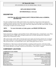
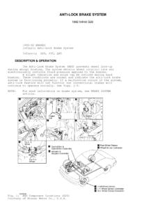
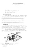
1 anti -LOCKBRAKESYSTEMR eturn To Main Table of ContentsGENERAL .. 2 ABS MODULATOR AND ABS RELAY ..9 ABSCM (ABS Control Module) ..11 WHEEL SPEED SENSOR ..12 BLEEDING OF BRAKE SYSTEM ..14 TROUBLESHOOTING ..15 GENERALGENERALSPECIFICATIONSABSCM ( ANTI-LOCK BRAKE SYSTEM Control Module)Operating voltage rangePower consumptionController fuseOperating temperature rangeABS Service Reminder IndicatorPower consumptionService Reminder Indicator fuseModulatorOperating voltage rangeRated voltagePump Motor fuseSolenoid fuseOperating temperature mA or below10A-40o to + C to 120 CTIGHTENING mounting bolt on the BRAKE plateFrontRearHydraulicunitmountingboltH ydraulicunitmountingbracketboltSix BRAKE tubes on the Hydraulic Unit7-1170-1105-817-26170-26012-1917-261 70-26012-1917-26170-26012-1913-17130-170 9-12 GENERAL58A-3 SYSTEM COMPONENTThe ANTI-LOCK BRAKE SYSTEM (ABS)
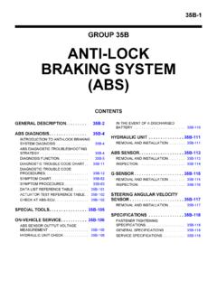
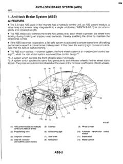
2 Controls the hydraulic BRAKE pressure of all four wheels during sudden braking andbraking on hazardous road surfaces, preventing the wheels from locking. The ABS provides the following benefits:(1) Enables steering around obstacles with a greater degree of certainty even during panic braking(2) Enables stopping during panic braking while allowing stability and steerability to a minimum, even on case a malfunction occurs, a diagnosis function and fail-safe SYSTEM have been included for DIAGRAM (1)GENERAL58A-5 WIRING DIAGRAM (2)GENERALWIRING DIAGRAM (3)GENERALHYDRAULIC SYSTEM DIAGRAMDIAGRAM58A-8 GENERALABSCM CONNECTORI : INPUTO : OUTPUTF/SF : Fail safeSRI : Service Reminder IndicatorDLC : Data Link ConnectorModulator connector (E57)Relay Box connector (E58)ABS MODULATOR AND ABS RELAY58A-9 ABS MODULATOR AND ABS RELAYCOMPONENTSM odulator mounting bracket17-26(170-260,12-19)TIGHTENING TORQUE.
3 ( , ) the Air cleaner the ABS Relay box harness, Motor Pump harnessand modulator the BRAKE tubes from the ABS modulator to thebrake master cylinder and proportioning MODULATOR AND ABS the Relay box from modulator mounting the Modulator mounting Bracket and remove attempt to disassemble the ABS modulator must be transported and stored inupright position and with sealed modulator must not be the reverse order of the modulator mounting bolts and BRAKE tube nuts tothe specified torqueModulator mounting (170-260 kgcm, 12-19 lb) BRAKE tube nut ..13-17 (130-170 , 9-12 lb)ABSCM (ABS control module)58A-11 ABSCM (ABS Control Module)2. Remove the the luggage side trim58A-12 WHEEL SPEED SENSORWHEEL SPEED SENSORTIGHTENING TORQUEREMOVAL1.
4 Disconnect the wheel speed sensor connector and SPEED SENSOR 58A-13 INSPECTION1. Connect an ohmmeter between the wheel speed sensor termi-nals and measure the standard : Front : 1275-1495 Rear : 1260-15402. Connect a voltmeter between the wheel speed sensor termi-nals, and measure the voltage by turning the the voltmeter to measure AC standard : AC voltage OF BRAKE SYSTEMBLEEDING OF BRAKE SYSTEMNOTET here are no special bleeding procedure for the ABS SYS-TEM. For bleeding please use the standard rules as describedfor the conventional BRAKE SYSTEM as OF BRAKE the reservoir cap and fill the BRAKE reservoir withbrake not allow BRAKE fluid remain on a painted it off bleeding by pressurized fluid, do not depress thebrake the vinyl tube to the wheel cylinder bleeder screw, andinsert the other end of tube in a half full container of BRAKE pump the BRAKE pedal several depressing the BRAKE pedal fully, loosen the bleederscrewuntil fluid starts to run out.
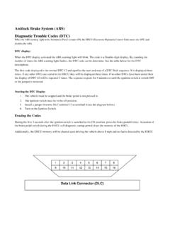
5 Then close the bleeder the 3 and 4 until there are no more bubbles in the the bleeder plug screw tightening torque ..Front :7-13 Nm (70-130 , 5-10 )Rear :8-20 Nm (80-200 , 6-15 )Repeat the above procedure for each wheel in the sequenceshown in the 58A-15 SYSTEM DIAGNOSIS STEPINDICATOR CHECKWhen the ignition switch is turned on, check that the ABS SRI goesON for 6 the SRI is not illuminated immediately after ignition on, the ABSfail safe relay may be at TOOL CHECK1. Turn the ignition Connect the scan tool to the data link connector in the fuse Connect the power-source terminal of the scan tool to thecigarette lighter Turn the ignition Use the scan tool to check the self-diagnosis After completion of the repair or correction of the problems, turnOFF the ignition switch; then erase the stored diagnostictrouble codes using the scan Disconnect the scan CHECK1.
6 Remove the battery negative (-) Disconnect the connectors and check the terminals followingthe troubleshooting performing the test procedures, be careful not todamage the connector Servicereminder indicatorAnti-lock BRAKE systemGROUNDDATA LINK CONNECTORTROUBLESHOOTINGD iagnostic trouble code chartDiagnostictroublecode Tool displayDiagnosis itemDescription19 TONE WHEEL21 SOL. LF-SHRTCHECK THE TONEWHEELSLEFT FRONT SOLENOIDC heck for a defective tone wheel on for short circuit to +I2 Volt forthe left front LF-OPENLEFT FRONT SOLENOIDD etection for open circuit or short circuit toGND for the left front RF-SHRTRIGHT RIGHT SOLENOIDD etection for short circuit to +12 Volt forthe right front RF-OPENRIGHT FRONT SOLENOIDD etection for open circuit or short circuit toGND for the right front LR-SHRTLEFT REAR SOLENOIDD etection for short circuit to +I2 Voltfor the left rear LR-OPENLEFT REAR SOLENOIDD etection for open circuit or short circuit toGND for the left rear RR-SHRTRIGHT REAR SOLENOIDD etection for short circuit to +I2 Voltfor the right rear RR-OPENRIGHT REAR SOLENOIDD etection
7 For open circuit or short circuit toGND for the right rear LF-GAPLEFT FRONT SENSORD etection for the air gap of the tone detection will be activated if all wheelspeeds are zero and the ABS-function is RF-GAPRIGHT FRONT SENSORD etection for the air gap of the tone detection will be activated if all wheelspeeds are zero and the ABS-function is LR-GAPLEFT REAR SENSORD etection for the air gap of the tone detection will be activated if all wheelspeeds are zero and the ABS-function is RR-GAPRIGHT REAR SENSORD etection for the air gap of the tone detection will be activated if all wheelspeeds are zero and the ABS-function is PUMPMOTOR PUMPF aulty or seized up motor Tool displayDiagnosis itemDescription36MP RLY-OPENMOTOR RELAY CIRCUITD etection for a open circuit or a shortcircuit to GND from the motor pump RLY-SHRTMOTOR RELAY CIRCUITD etection for a short circuit to +12 Voltfrom the motor pump BATT-SHRT39MP GND-SHRT41 FAIL RLY-SHRTFAIL RLY-OPENPUMP MOTORPUMP MOTORFAIL SAFE RELAYFAIL SAFE RELAYD etection for a short circuit at the motorpumpDetection for a short circuit to GND at themotor pumpFail safe relay contacts are short safe relay contacts are open circuit43 FAIL COILFAIL SAFE RELAY COILThe current from the fail safe relay is toohigh or too low44 ABS SRI-GNDD etection of a short circuit of the ServiceReminder Indicator (Permanently on)
8 45 ABS SRI-DIODED etection for a open circuit of the diode forthe Service Reminder Indicator SRI-BATTD etection for a short circuit to +12V ofthe Service Reminder SRI-OPEND etection for a open circuit of the ServiceReminder Indicator VOLT-LOSERVICE REMINDERINDICATORSERVICE REMINDERINDICATOR DIODESERVICE REMINDERINDICATORSERVICE REMINDERINDICATORBATTERY VOLTAGEB attery voltage out of the function range(Under voltage) for the VOLT-HIBattery voltage out of the function range(Over voltage) for the LF-OPENS ensor open circuit or short to 12 Voltdetection for the left front wheel63 SNSR. RF-OPENBATTERY VOLTAGELEFT FRONT SENSORCIRCUITRIGHT FRONT SENSORCIRCUITLEFT REAR SENSORCIRCUITS ensor open circuit or short to 12 Voltdetection for the right front LR-OPENS ensor open circuit or short to 12 Voltdetection for the left rear RR-OPENSNSR.
9 LF-SHRTRIGHT REAR SENSORCIRCUITLEFT FRONT SENSORCIRCUITS ensor open circuit or short to 12 Voltdetection for the right rear short to GND detection for the leftfront wheel58A-18 TROUBLESHOOTINGD iagnostictroublecode Tool displayDiagnosis itemDescriptionSensor short to GND detection for theright front short to GND detection for theleft rear short to GND detection forthe right rear for missing teeth on the tonewheel or speed jumps over-100g on theleft front for missing teeth on the tonewheel or speed jumps over-100g on theright front for missing teeth on the tonewheel or speed jumps over-100g on theleft rear for missing teeth on the tonewheel or speed jumps over-100g on theright rear of a ABSCM (ABS Controlmodule) RF-SHRTRIGHT FRONT SENSORCIRCUITLEFT REAR SENSORCIRCUITRIGHT REAR SENSORCIRCUIT68 SNSR.
10 LR-SHRTSNSR. RR-SHRTSNSR. LF-S. JMPSNSR. FRONT TONE WHEEL71 RIGHT FRONT TONEWHEEL72 LEFT REAR TONE WHEEL7374 RIGHT REAR TONEWHEEL77 ABSCM-FAILABSCM ERRORACTUATOR TEST- Test condition : Ignition ON -SCAN TOOL (MUT) DISPLAYRECOGNITIONREMARKSF ront left solenoid valve operation(Click sounds)Actuation time is limited toMAX. 20 seconds21. SOLENOID - LF23. SOLENOID - RF25. SOLENOID - LRFront right solenoid valve operation(Click sounds)Rear left solenoid valve operation(Click sounds)Rear right solenoid valve operation(Click sounds)Motor pump relay operation(Click sounds)27. SOLENOID - RR36. MP. RLY99. ACT. TST. STOPStop actuator test58A-19 SERVICE DATASCAN TOOL (MUT) DISPLAY21. SOLENOID-LFON or OFFDESCRIPTIONLeft front solenoid valve operation statusREMARKS23.