Transcription of AP212 Gear Pumps - Bucher Hydraulics
1 1/60 Reference: 200-P-991230-EN-05 Issue: Gear Pumps Standard and Low Noise series200-P-991230-EN-05 gear Pumps of typical sound pressure level recorded in a semi-anechoic testing the rotation symbols used in the Calculating the specification of a gear Diagrams standard Single pump customised pump customised versions order pump end gear Pumps dimensions (standard version without shaft seal between the Pumps ) Pumps dimensions (special version with shaft seal between the Pumps ) Pumps dimensions (standard version without shaft seal between the Pumps ) Pumps dimensions (special version with shaft seal between the Pumps ) to order tandem Pumps (with or without shaft seal between the Pumps ) to order triple Pumps (with or without shaft seal between the Pumps ) Pumps dimensions AP212 + AP100 (with shaft seal between the Pumps ) to order tandem Pumps AP212 + AP100 (with shaft seal between the Pumps )
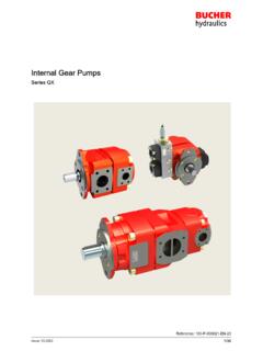
2 Sensing 200-P-991230-EN-05 changing seal kit NBR + HNBR standard identification informationThe product range of Bucher Hydraulics SpA includessingle Pumps 05-100-212-212HP-250-300 (correspondingwith the common group denominations: ) andseveral combinations of double Pumps , triple Pumps , andso on, that can be assembled together according to versions of displacement, flanging, and auxiliary valves .External gear Pumps are widely used in modern hydraulicsystems due to their high performance, long service life andlow purchase and maintenance following we introduce you the new AP212 development of the new AP212 family has made itpossible to achieve high operating pressures, excellentvolumetric and mechanical efficiency and on specially de veloped units (LN Low Noise) even lower noise has been possible by means of.
3 -new design of gear teeth and balancing areas-use of high-performance materials-carefully controlled heat treatments-increasingly tight coupling tolerances and a high standard of surface finish-continuous development in our semi-anechoic roomBucher Hydraulics has so achieved these results byconstantly improving its design, control and manufacturingtechniques inline with the latest technological develop ments, while simultaneously enhancing our Quality ControlSystem which ensures that every single product offers thesame high standards.
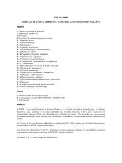
4 200-P-991230-EN-05 External gear Pumps components3214758995610111213641. Retaining ring2. Shaft seal3. Front cover4. Balancing seal5. Back up seal6. Balancing block7. Drive gear8. Driven gear9. Oil seal10. Centering pin11. Pump body12. Back cover13. Fixing screw and (New AP212 vs AP200)Front covers :In addition to aluminium versions, complete new range ofcast iron front coversBalancing blocks :New generation optimised and standardised balancingblocksGears :New gears profile (12 teeth) with increased transmissibletorqueBodies:New design pump bodiesBack covers.
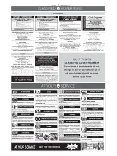
5 Wide range of aluminium and cast iron back covers with/without integrated cartridge valvesGEAR PUMPSF luid-borne noiseStructural-bornenoiseAirborne noiseTARGETFlow pulsationreductionVibration reductionPump low noise levelHYDRAULIC CIRCUIT200-P-991230-EN-05 18 12 20 2012H = 15-18-21H = 21H = 21 HTimeTime/2 PulsationPulsationreducedPulsation/4-75% Measurementsin mm12 = numberof newoptimisedteethAP212 optimised balancingarea with higher performancematerialsAP200 Standard gear pumpAP212 Gear pumpAP212 Low Noise gear Example of typical sound pressure level recorded in a semi-anechoic testing room5055606570050100150200250 Pressure [bar]LAeq [dB(A)]AP200/15AP212/15AP212/15 LNNoise reduction effectsOil temperature: 40 C - Oil viscosity: 32 mm2/sDistance between pump and sensor: 1 mSpeed: 1500 rpm 200-P-991230-EN-05 Technical dataFeaturesOperating fluid temperature range (mineral oil):NBRHNBR-15 / +80 C (peak: -20 / +90 C)-20 / +90 C (peak: -30 / +110 C)Recommended fluidshydraulic mineral oil-basedViscosity range.
6 RecommendedPermittedPermitted for starting20-120 mm2/s (cSt)12- 700 mm2/s (cSt)2000 mm2/s (cSt)Cleanliness:recommended up to 140 bar (2000 PSI)recommended up to 210 bar (3000 PSI)recommended up to 275 bar (4000 PSI)20/18/15 ISO 440619/17/14 ISO 440617/15/12 ISO 4406 Minimum storage temperature:NBRHNBR-25 C-35 CStandard seals material (valves not included)NBR + HNBR standard ( ISO1629)AP/APR212 DisplacementAP/APR212 LNDisplacementMax. pressure*n <100 barn <n<180 barn <n< (continuous)P2(intermittent)P3(peak) ** ** * Referred to Pumps with flanged ports.
7 Utilising threaded ports, please toconsider a significantly de-rated performances. The mechanical stress localised on threaded ports cause a reduced pumplife performances** obtained with a specific balancing plate, please contact our Sales CenterIMPORTANT!: Please consult Bucher Hydraulics if even one of the operating limits indicated in the table (tempera ture, pressure, rpm) is exceeded, as well as in the case of two or more maximum values at the same time, or forapplications with particularly heavy-duty PressurePressure levels:P1 = continuous pressureP2 = intermittent pressureP3 = peak pressureThe recommended oil speed in the pressure pipes is:v = 2 to 5 m/sP1P2P3t (s)p (bar)max.
8 15 s200-P-991230-EN-05 SuctionThe absolute suction pressure must be Pin bar (11 PSI); therefore, the following conditions must beavoided:- large height differences between pump and tank- long stretches of piping- special features such as:- bends- reductions in diameter- quick couplings- is also advisable to choose a filter of a suitable size to minimise any pressure drop and to take measures to pre vent gradual clogging over time.(Example 1)In certain cases, the suction pressure can exceed 1 bar( PSI), or atmospheric contact our Sales Department, solution forPin bar (50 PSI) , are in a particular application the Pin pressure is higher thanthe recommended value, contact our Sales diameter of the suction pipe should ensure that the oilspeed will fall within the range: v = - m/s.
9 (Example 2)MM(Example 1)(Example 2) General precautionIn addition to the recommendations regarding fluids, filtra tion, coupling, etc., we suggest the following:- Always check the rotation direction of the pump'sdrive shaft; it must be compatible with the rotationdirection of the pump Be particularly careful in cleaning and make sure,when connecting the suction and pressure piping,that no chips, rag threads, teflon tape, etc. get into thepump circulation Check the tightness of the suction and pressure fit tings, the correct positioning of the O-Ring, and makesure there is no dirt between the flange and the The first pump start-up can be facilitated by manuallyfilling the suction piping and the pump itself with facilitate air bleeding, start the pump with the cir cuit not To ensure the best heat distribution inside the tank,make sure the return pipe is not too close to thepump's suction piping.
10 The pipings themselvesshould be below oil tank level to prevent the forma tion of Do not subject the Pumps to operating conditions different from those indicated on section ; for extreme operations, always contact our Never use fluids different from those indicated in sec tion and do not use fluids incompatible with thepump seals ( HNBR)- In the event of pump painting, do not use solvents orpaints that are incompatible with the material of theseals. Do not bake paint with excessively high tem peratures.