Transcription of APC Smart-UPS X-Series 2000/2200/3000 VA Operation Manual
1 Operation ManualSmart-UPS XUninterruptible power SupplyLow Voltage (100-127 V)SMX2000 RMLV2 USMX2200 RMLV2 USMX3000 RMLV2 USMX3000 RMLV2 UNCSMX3000 RMJ2 UHigh Voltage (200-240 V)SMX2200 RMHV2 USMX3000 RMHV2 USMX3000 RMHV2 UNC1 Smart-UPS X 2000/2200/3000 VA OverviewAbout the UPSThe APC by Schneider Electric Smart-UPS X is a high performance uninterruptible power supply (UPS). It provides protection for electronic equipment from utility power blackouts, brownouts, sags, and surges; small utility fluctuations and large disturbances.
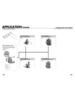
2 The UPS also provides battery backup power until utility power returns to safe levels or the batteries are fully Smart-UPS X has both high and low voltage modelsSafetyRead the Safety Guide included in the package before installing the the UPS upon receipt. Notify the carrier and dealer if there is the : The external battery packs (XLBPs) are heavy. Always install the XLBPs at the bottom of the rack. Install the UPS above the installed OverviewFront panelLow Voltage (100-127 V)High Voltage (200-240 V)SMX2000 RMLV2 USMX2200 RMHV2 USMX2200 RMLV2 USMX3000 RMHV2 USMX3000 RMLV2 USMX3000 RMHV2 UNCSMX3000 RMLV2 UNCSMX3000 RMJ2U Battery Battery connector Display interface Bezelsu0498aSmart-UPS X 2000/2200/3000 VA 2 Rear panelSpecificationsOperating ConditionsThis unit is intended for indoor use only.
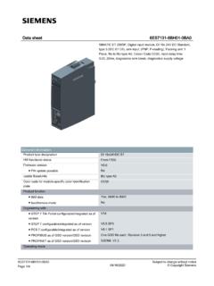
3 Select a location sturdy enough to support the weight of the UPS and not operate the unit where there is excessive dust, or the temperature or humidity are outside the specified unit has front and rear air vents. Allow adequate space for proper SpecificationsEnvironmental factors impact battery life. High temperatures, poor utility power , and frequent, short duration discharges will shorten battery additional specifications, see the APC Web site at SmartSlot Controllable Outlet Group 3 UPS input External battery pack connector Ground screw EPO connector Controllable Outlet Group 1 Serial port Controllable Outlet Group 2 USB port2200 VA Low Voltage2000 VA Low Voltage3000 VA Low Voltage2200/3000 VA High VoltageTe m p e r a t u r eOperating0 to 40 C (32 to 104 F)
4 Storage-15 to 45 C (5 to 113 F)charge UPS battery every six monthsMaximumElevationOperating3,000 m (10,000 ft)Storage15,000 m (50,000 ft)Humidity0% to 95% relative humidity, non-condensingsu0494asu0492asu0495asu049 3a3 Smart-UPS X 2000/2200/3000 VA InstallationUPSFor UPS installation information, see the Smart-UPS X 2000-3000 VA Quick-Start that is included with the UPS. The guide is also available on the enclosed CD and the APC Web site at Management CardFor installation information, see the user Manual provided with the Network Management Card (NMC).
5 The user Manual is also available on the APC Web site at Battery PackFor installation information, see the Smart-UPS X 2000-3000 VA External Battery Pack Installation guide that is included with the external battery pack. The guide is also available on the enclosed CD and the APC Web site at X 2000/2200/3000 VA 4 OperationConnect Equipment to the UPSNote: The UPS will charge to 90% capacity in the first three hours of normal Operation . Do not expect full battery runtime capability during this initial charge Connect equipment to the outlets on the rear panel of the UPS.
6 2. Connect the UPS to the building utility power . Connect the UPS to a two-pole, three-wire, grounded source Press the ON/OFF button on the front panel of the UPS to power the unit and all connected equipment. 4. To use the UPS as a master on/off switch, turn on all the equipment that is connected to the Switched Outlet Groups on page 11 for information on how to use the Switched Outlet ConnectionsSerial port: Connect to a computer to use power management software, use the serial cable included with the unit.
7 USB port: Connect to a computer to use power management software. Note: Serial and USB communication can only be used individually, they cannot communicate at the same Battery Pack connector: Connect XLBPs to provide extended runtime during power outages. The UPS can support up to 10 external battery Screw: The UPS features a ground screw for connecting the ground leads on transient voltage devices. Prior to connecting a ground lead, disconnect the UPS from utility X 2000/2200/3000 VA Display InterfaceOverviewUsing the display interfaceUse the UP and DOWN buttons to scroll through the main menu options.
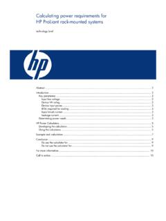
8 Press ENTER to view the sub-menus under each main menu option. Press ESCAPE to exit a sub-menu and return to a main OverviewThe Smart-UPS has Standard and Advanced menu screens. The Standard menu screens are the most commonly used screens. The Advanced menu screens are for more advanced users to configure additional features on the : Actual menu screens may differ by model. Online LED UPS Output On/Off button On Battery LED Fault LED Replace Battery LED Display screen UP and DOWN buttons ENTER button ESCAPE buttonMain MenuOverviewStandardAdvancedScrolling ScreensOn Utility (the UPS is operating on utility power )xOutlet Group StatusxInput and Output voltagexLoad meterxBattery charge and runtimexWa r n i n g sxLoad and Battery graphsxStatusOperating ModexxEfficiency in % (Green mode only)xxInput and output voltagexxLoad power (W)
9 And VAxxsu0343aAPC By SchneiderElectricSmart-UPS X 2000/2200/3000 VA 6 Load (A)xLoad meter (kWh)xLast transfer to battery power informationxxBattery charge and estimated run timexxBattery voltagexNumber of external battery packsxInternal battery temperaturexRun time calibration test resultsxxSelf-test resultsxxStatus of the switched outlet group(s): On, Off, Sleep, Reboot, Turning On, Turning OffxSmart Slot information (if applicable)xConfigurationLanguagexxLocal power qualityxxStandard or Advanced menusxxAudible alarmsxxHigh and low transfer pointsxLow run time warningxGreen mode (enable/disable)xOutput voltagexxBattery self-test intervalxxBattery installation datexxUPS firmware update (only available when output is off)xxUPS setup wizardxxReset to factory defaultsxxSwitched outlet group(s)
10 Delays and settingsxSmart Slot configuration (if applicable)xControlSwitched outlet group(s): Turn on, turn off, put to sleep, or rebootxTest & DiagnosticsUPS calibration and display about transfers to battery power , time on battery, and total operating timexLogsTransfer logxStatus logxFault logxMain MenuOverviewStandardAdvanced7 Smart-UPS X 2000/2200/3000 VA AboutGeneral information about the UPS, including: model numbers, output voltage setting, serial number, manufacture date, replacement battery cartridge information, firmware versions, and suggested battery replacement card information (if applicable), including IP addressxPowerChute Business Edition information (if applicable)xMain MenuOverviewStandardAdvancedSmart-UPS X 2000/2200/3000 VA 8 ConfigurationUPS SettingsStart-up SettingsUse the display interface to configure these settings at initial start-up.