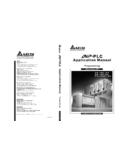
Transcription of Application Manual DVP-PLC Application Manual
1 DVP-PLC Application ( Programming ) DVP-PLC Application Manual ( Programming ) 20130530 Industrial Automation HeadquartersDelta Electronics, Inc. Taoyuan Technology , Xinglong Rd., Taoyuan City, Taoyuan County 33068, TaiwanTEL: 886-3-362-6301 / FAX: 886-3-371-6301 AsiaDelta Electronics (Jiangsu) Plant 31688 Jiangxing East Road, Wujiang Economic Development ZoneWujiang City, Jiang Su Province, People's Republic of China (Post code: 215200)TEL: 86-512-6340-3008 / FAX: 86-769-6340-7290 delta Greentech (China) Co., Min-Xia Road, Pudong District, ShangHai, code : 201209 TEL: 86-21-58635678 / FAX: 86-21-58630003 delta Electronics (Japan), Office 2-1-14 Minato-ku Shibadaimon, Tokyo 105-0012, JapanTEL: 81-3-5733-1111 / FAX: 81-3-5733-1211 delta Electronics (Korea), , Byucksan Digital Valley 6-cha, Gasan-dong, Geumcheon-gu, Seoul, Korea, 153-704 TEL: 82-2-515-5303 / FAX: 82-2-515-5302 delta Electronics Int l (S) Pte Ltd4 Kaki Bukit Ave 1, #05-05, Singapore 417939 TEL: 65-6747-5155 / FAX: 65-6744-9228 delta Electronics (India) Pvt.
2 No 43 Sector 35, HSIIDC Gurgaon, PIN 122001, Haryana, India TEL : 91-124-4874900 / FAX : 91-124-4874945 AmericasDelta Products Corporation (USA)Raleigh Box 12173,5101 Davis Drive, Research Triangle Park, NC 27709, : 1-919-767-3800 / FAX: 1-919-767-8080 delta Greentech (Brasil) Paulo OfficeRua Itapeva, 26 - 3 andar Edificio Itapeva One-Bela Vista01332-000-S o Paulo-SP-BrazilTEL: +55 11 3568-3855 / FAX: +55 11 3568-3865 EuropeDeltronics (The Netherlands) OfficeDe Witbogt 15, 5652 AG Eindhoven, The Netherlands TEL: 31-40-2592850 / FAX: 31-40-2592851 DVP-0959720-04*We reserve the right to change the information in this catalogue without prior notice. DVP-PLC Application Manual : Programming Table of Contents Chapter 1 Basic Principles of PLC Ladder Diagram Foreword: Background and Functions of 1-1 The Working Principles of Ladder 1-1 Differences Between Traditional Ladder Diagram and PLC Ladder Diagram.
3 1-2 Edition Explanation of Ladder Diagram .. 1-3 How to Edit Ladder Diagram .. 1-8 The Conversion of PLC Command and Each Diagram Structure .. 1-12 Simplified Ladder 1-15 Basic Program Designing 1-17 Chapter 2 Functions of Devices in DVP-PLC All Devices in 2-1 Values, Constants [K] / [H] .. 2-9 Numbering and Functions of External Input/Output Contacts [X] / [Y].. 2-10 Numbering and Functions of Auxiliary Relays [M] .. 2-14 Numbering and Functions of Step Relays [S] .. 2-14 Numbering and Functions of Timers [T] .. 2-16 Numbering and Functions of Counters [C] .. 2-18 Numbering and Functions of Registers [D], [E], [F] .. 2-33 Data register [D] .. 2-33 Index Register [E], [F].
4 2-34 Functions and Features of File Registers .. 2-34 Pointer [N], Pointer [P], Interruption Pointer [I] .. 2-35 Special Auxiliary Relays and Special Data Registers .. 2-39 Functions of Special Auxiliary Relays and Special 2-88 Communication Addresses of Devices in DVP Series 2-155 Error Codes .. 2-157 Chapter 3 Basic Instructions Basic Instructions and Step Ladder 3-1 Explanations on Basic Instructions .. 3-3 Chapter 4 Step Ladder Instructions Step Ladder Instructions [STL], [RET] .. 4-1 Sequential Function Chart (SFC) .. 4-2 How does a Step Ladder Instruction Work? .. 4-3 Things to Note for Designing a Step Ladder 4-8 Types of 4-10 IST Instruction.
5 4-18 Chapter 5 Categories & Use of Application Instructions List of Instructions .. 5-1 Composition of Application Instruction .. 5-9 Handling of Numeric 5-14 E, F Index Register Modification .. 5-16 Instruction Index ..5-18 Chapter 6 Application Instructions API 00-49 API00 ~ 09 Loop 6-1 API10 ~ 19 Transmission Comparison .. 6-20 API20 ~ 29 Four Arithmetic Operation .. 6-37 API30 ~ 39 Rotation & Displacement .. 6-52 API40 ~ 49 Data Processing .. 6-63 Chapter 7 Application Instructions API 50-88 API50 ~ 59 High Speed 7-1 API60 ~ 69 Handy Instructions .. 7-42 API70 ~ 79 Display of External 7-74 API80 ~ 88 Serial 7-97 Chapter 8 Application Instructions API 100-149 API100 ~ 109 Communication.
6 8-1 API110 ~ 119 Floating Point Operation .. 8-22 API120 ~ 129 Floating Point 8-37 API130 ~ 139 Floating Point 8-49 API140 ~ 149 Others .. 8-61 Chapter 9 Application Instructions API 150-199 API150 ~ 154 Others .. 9-1 API155 ~ 159 Position Control .. 9-29 API160 ~ 169 Real Time 9-60 API170 ~ 179 Gray Code Conversion/Floating Point Operation .. 9-72 API180 ~ 190 Matrix .. 9-90 API190 ~ 199 Positioning Instruction .. 9-106 Chapter 10 Application Instructions API 202-313 API202 ~ 207 Others.. 10-1 API215 ~ 223 Contact Type Logic Operation Instruction.. 10-16 API224 ~ 246 Contact Type Comparison Instruction .. 10-19 API266 ~ 274 Word Device Bit Instruction.
7 10-26 API275 ~ 313 Floating-point Contact Type Comparison 10-32 Chapter 11 Appendix Appendix A: Table for Self-detecting Abnormality .. 11-1 Appendix B: MPU Terminal 11-2 Appendix C: Terminal Layout for Digital I/O 11-6 Appendix D: Difference between EH2 and EH3 .. 11-9 Appendix E: Current Consumption of a Slim PLC/an Extension Module .. 11-10 Appendix F: Current Consumption of an EH2/EH3 Series PLC/an Extension 11-12 Appendix G: Using Ethernet Communication ..11-14 Appendix H: Revision History .. 11-27 The models that every series includes are as follows. Series Model name DVP-ES DVP14ES00R2, DVP14ES00T2, DVP14ES01R2, DVP14ES01T2, DVP24ES00R, DVP24ES00R2, DVP24ES00T2, DVP24ES01R2, DVP24ES01T2, DVP24ES11R2, DVP30ES00R2, DVP30ES00T2, DVP32ES00R, DVP32ES00R2, DVP32ES00T2, DVP32ES01R2, DVP32ES01T2, DVP40ES00R2, DVP40ES00T2, DVP60ES00R2, DVP60ES00T2 DVP10EC00R3, DVP10EC00T3, DVP14EC00R3, DVP14EC00T3, DVP16EC00R3, DVP16EC00T3, DVP20EC00R3, DVP20EC00T3, DVP24EC00R3, DVP24EC00T3, DVP30EC00R3, DVP30EC00T3, DVP32EC00R3, DVP32EC00T3, DVP40EC00R3, DVP40EC00T3, DVP60EC00R3, DVP60EC00T3, DVP-EX DVP20EX00R2, DVP20EX00T2, DVP20EX11R2 DVP-SS DVP14SS11R2, DVP14SS11T2 DVP-SA DVP12SA11R, DVP12SA11T DVP-SX DVP10SX11R.
8 DVP10SX11T DVP-SC DVP12SC11T DVP-EH2 DVP16EH00R2, DVP16EH00T2, DVP20EH00R2, DVP20EH00T2, DVP32EH00M2, DVP32EH00R2, DVP32EH00T2, DVP40EH00R2, DVP40EH00T2, DVP48EH00R2, DVP48EH00T2, DVP60EH00T2, DVP64EH00R2, DVP64EH00T2, DVP80EH00R2, DVP80EH00T2, DVP32EH00R2-L, DVP32EH00T2-L DVP-SV DVP28SV11R, DVP28SV11T DVP-EH3 DVP16EH00R3, DVP16EH00T3, DVP20EH00R3, DVP20EH00T3, DVP32EH00M3, DVP32EH00R3, DVP32EH00T3, DVP40EH00R3, DVP40EH00T3, DVP48EH00R3, DVP48EH00T3, DVP60EH00T3, DVP64EH00R3, DVP64EH00T3, DVP80EH00R3, DVP80EH00T3, DVP32EH00R3-L, DVP32EH00T3-L DVP-SV2 DVP28SV11R2, DVP28SV11T2 1 Basic Principles of PLC Ladder Diagram DVP-PLC Application Manual 1-1 Foreword: Background and Functions of PLC PLC (Programmable Logic Controller) is an electronic device, previously called sequence controller.
9 In 1978, NEMA (National Electrical Manufacture Association) in the United States officially named it as programmable logic controller . PLC reads the status of the external input devices, keypad, sensor, switch and pulses, and execute by the microprocessor logic, sequential, timing, counting and arithmetic operations according the status of the input signals as well as the pre-written program stored in the PLC. The generated output signals are sent to output devices as the switch of a relay, electromagnetic valve, motor drive, control of a machine or operation of a procedure for the purpose of machine automation or processing procedure. The peripheral devices ( personal computer/handheld programming panel) can easily edit or modify the program and monitor the device and conduct on-site program maintenance and adjustment.
10 The widely used language in designing a PLC program is the ladder diagram. With the development of the electronic technology and wider applications of PLC in the industry, for example in position control and the network function of PLC, the input/output signals of PLC include DI (digital input), AI (analog input), PI (pulse input), NI (numeric input), DO (digital output), AO (analog output), and PO (pulse output). Therefore, PLC will still stand important in the industrial automation field in the future. The Working Principles of Ladder Diagram The ladder diagram was a diagram language for automation developed in the WWII period, which is the oldest and most widely adopted language in automation.