Transcription of APPLICATION NOTE 5780 Designing Active-Clamp Forward ...
1 Keywords: error amplifier compensation, Active-Clamp Forward converter, peak-current-mode controller APPLICATION NOTE 5780. Designing Active-Clamp Forward Converters Using Peak-Current-Mode Controllers By: K S Bhanuprasad Aug 05, 2014, Maxim Integrated Products, Inc. Abstract: Active-Clamp Forward converter design using MAX17598/MAX17599 is outlined. Design methodology and calculations for components value selection are presented. Introduction This APPLICATION note describes the methodology of Designing Active-Clamp Forward converters using the MAX17598/MAX17599 peak-current-mode controllers.
2 This APPLICATION note discusses both self driven and winding driven secondary synchronous MOSFETs in the active- clamp Forward converter topology. Formulas for calculating component values and ratings are also presented. In this APPLICATION note, the following sections explain the design methodology of various components in the Active-Clamp Forward Converter topology. 1. Transformer Turns Ratio Selection 2. Output Inductor Selection 3. Primary Magnetizing Inductance Selection 4. Clamp Capacitor Selection 5. Input Capacitor Selection a.
3 Input Ceramic Capacitor Selection b. Filter Capacitor Selection in AC-DC Applications 6. Primary n-MOSFET Selection 7. Current-Sense Resistor Selection 8. Primary p-MOSFET Selection 9. p-MOSFET Gate-Drive Circuit for Low-Side Active-Clamp Configuration 10. SLOPE Compensation 11. IN Supply Configuration a. IN Supply Configuration for Offline/Telecom Power-Supply Design b. IN Supply Configuration for Low-Voltage DC-DC Converters 12. Secondary Rectifier Configuration a. Self-Driven Synchronous MOSFETs b. Winding Driven Synchronous MOSFETs c.
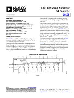
4 DIODE Rectifier 13. Output Capacitor Selection Page 1. 14. Error Amplifier Compensation Design in Nonisolated Applications 15. Thermal Considerations 16. Isolated Active-Clamp Forward Converter with Optocoupler Feedback 17. MAX17598 Typical Operating Circuit 18. Design Example Active-Clamp Forward Converter Using MAX17598. 19. Bill of Materials (BOM). Typical APPLICATION Circuit VIN. VOUT. L1 D1. L2. VOUT. T1. C7 D2. R1 NB. R2. VDC. R3. C5 C4 C6. NS N1. INPUT. PGND NP. C2 C3. P GND 0. N2. PGND VIN PGND 0. C8 C10. U1 PGND.
5 VOUT. C16. VIN. C11. SS. AUXDRV P1. R 20. SLOPE. R 12 VDRV. NDRV N3 R 10 R 11. R 18 U2. R 14 4. RT 1. C18. PGND. SGND D4 VFB C13. R 16. DITHER / 2. SYNC CS SGND 3. R 19. C15 R 21. D3 C14. SGND. VOUT. R 17. SGND R 13. SGND MAX17598. R 23 C20 2. VDRV U3. PGND. 1. R6 3. C19 VDRV SGND. VDC COMP PGND 0. VFB R 22. C9. C1. R 24. PGND. FB. R8. R5. DT PGND 0. EN /UVLO. R7 EP. OVI. SGND. R4. SGND. Figure 1. MAX17598 APPLICATION schematic. 1. Transformer Turns Ratio Selection (k = Ns/Np). Transformer turns ratio is selected so the output voltage is well regulated across the input voltage range.
6 The maximum operating duty cycle (DMAX) is chosen to be less than the absolute maximum duty cycle of the MAX17598/MAX17599 ICs ( , typical). VOUT. Transformer turns ratio, k =. VDCMIN DMAX. where DMAX (63%, typical) is the assumed maximum duty cycle at minimum input voltage VOUT. Minimum duty cycle at maximum input voltage can be calculated as, DMIN =. VDCMAX k Page 2. VOUT. Typical duty cycle at nominal input voltage can be calculated as, DTYP =. VDCTYP k where VOUT is output voltage, VDCMIN, VDCTYP, and VDCMAX are minimum, nominal, and maximum input voltages, respectively.
7 2. Output Inductor Selection The output inductance is calculated assuming a maximum peak-to-peak output current ripple (. I SEC ), which occurs at maximum input voltage. The output inductance can be calculated as follows: VOUT (1 DMIN ). L2 = Henry I OUT % I SEC f SW. where % I SEC ( , typical) is the ratio of peak-to-peak output inductor current ripple to the average output current at maximum input voltage, IOUT is rated output current in Amperes, fSW is the switching frequency in Hz The maximum and minimum peak-to-peak output current ripple, maximum secondary peak current can be back calculated for the chosen value of !
8 As follows: Minimum peak-to-peak output inductor current ripple, I SEC , MIN = VOUT (1 DMAX ) Ampere L2 f SW. Maximum peak-to-peak output inductor current ripple, I SEC , MAX V (1 DMIN ) Ampere = OUT. L2 f SW. I SEC ,MAX. Maximum output peak current, I SEC , PEAK = I OUT + Ampere 2. 3. Primary Magnetizing Inductance Selection The converter is a peak current-mode controller that controls the peak current as seen by the current-sense resistor, which is the sum of the reflected load current and magnetizing current. It is necessary that the magnitude of reflected load current is always more than the magnetizing current for stable converter operation and well regulated output.
9 This condition is always satisfied, if the magnitude of reflected load current at the input minimum is more than the magnetizing current. Hence, peak-to-peak primary magnetizing current is assumed to be half of the reflected load current at minimum input voltage, I SEC , MIN k I MAG = Ampere 2. With the assumed peak-to-peak magnetizing current, magnetizing inductance can be calculated as: Page 3. VDCMAX DMIN. LMAG = Henry I MAG f SW. If selected LMAG value is chosen to be different from the above calculated value, then new peak- to-peak magnetizing current ripple can be calculated as follows: VDCMAX DMIN.
10 I MAG = Ampere LMAG f SW. I MAG. Maximum primary peak current, I PRI , PEAK = I SEC , PEAK k + Ampere 2. 4. Clamp Capacitor Selection The clamp capacitor (C10) helps in resetting the flux in the transformer core as well as helps absorb leakage inductance energy, and forms a complex pole-zero pair with the magnetizing inductance (LMAG) of the transformer, at a frequency fR. 1 DMAX. fR =. 2 LMAG C10. The value of the clamp capacitor for a 20% voltage ripple is calculated as: 2. I (1 DMIN ). C10 = MAG Farad VDCMAX f SW. The voltage stress on the clamp capacitor can be calculated as: VDCMAX.