Transcription of Application Note 83 Fundamentals of RS–232 Serial ...
1 Application Note 83 Fundamentals of RS 232 Serial CommunicationsAPPLICATION NOTE 83030998 1/9 Due to it s relative simplicity and low hardware overhead(as compared to parallel interfacing), Serial communica-tions is used extensively within the electronics , the most popular Serial communications stan-dard in use is certainly the EIA/TIA 232 E specifica-tion. This standard, which has been developed by theElectronic Industry Association and the Telecommu-nications Industry Association (EIA/TIA), is more popu-larly referred to simply as RS 232 where RS standsfor recommended standard.
2 In recent years, this suffixhas been replaced with EIA/TIA to help identify thesource of the standard. This paper will use the commonnotation of RS 232 in its discussion of the official name of the EIA/TIA 232 E standard is Interface Between Data Terminal Equipment and DataCircuit Termination Equipment Employing SerialBinary Data Interchange . Although the name maysound intimidating, the standard is simply concernedwith Serial data communication between a host system(Data Terminal Equipment, or DTE ) and a peripheralsystem (Data Circuit Terminating Equipment, or DCE ).
3 The EIA/TIA 232 E standard which was introduced in1962 has been updated four times since its introductionin order to better meet the needs of Serial communica-tion applications . The letter E in the standard s nameindicates that this is the fifth revision of the 232 SPECIFICATIONSRS 232 is a complete standard. This means that thestandard sets out to ensure compatibility between thehost and peripheral systems by specifying 1) commonvoltage and signal levels, 2)common pin wiring configu-rations, and 3) a minimal amount of control informationbetween the host and peripheral systems.
4 Unlike manystandards which simply specify the electrical character-istics of a given interface, RS 232 specifies electrical,functional, and mechanical characteristics in order tomeet the above three criteria. Each of these aspects ofthe RS 232 standard is discussed CHARACTERISTICSThe electrical characteristics section of the RS 232standard includes specifications on voltage levels, rateof change of signal levels, and line original RS 232 standard was defined in 1962. Asthis was before the days of TTL logic, it should not besurprising that the standard does not use 5 volt andground logic levels.
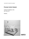
5 Instead, a high level for the driveroutput is defined as being +5 to +15 volts and a low levelfor the driver output is defined as being between 5 and 15 volts. The receiver logic levels were defined to pro-vide a 2 volt noise margin. As such, a high level for thereceiver is defined as +3 to +15 volts and a low level is 3 to 15 volts. Figure 1 illustrates the logic levelsdefined by the RS 232 standard. It is necessary to notethat, for RS 232 communication, a low level ( 3 to 15volts) is defined as a logic 1 and is historically referred toas marking.
6 Likewise a high level (+3 to +15 volts) isdefined as a logic 0 and is referred to as spacing .The RS 232 standard also limits the maximum slewrate at the driver output. This limitation was included tohelp reduce the likelihood of cross talk between adja-cent signals. The slower the rise and fall time, thesmaller the chance of cross talk. With this in mind, themaximum slew rate allowed is 30 V/ s. Additionally, amaximum data rate of 20k bits/second has been definedby the standard. Again with the purpose of reducing thechance of cross impedance of the interface between the driver andreceiver has also been defined.
7 The load seen by thedriver is specified to be 3k to 7k . For the originalRS 232 standard, the cable between the driver and thereceiver was also specified to be a maximum of 15meters in length. This part of the standard was changedin revision D (EIA/TIA 232 D). Instead of specifyingthe maximum length of cable, a maximum capacitiveload of 2500 pF was specified which is clearly a moreadequate specification. The maximum cable length isdetermined by the capacitance per unit length of thecable which is provided in the cable NOTE 83030998 2/9RS 232 LOGIC LEVEL SPECIFICATIONS Figure 1+3V 3 VRECEIVERINPUTTHRESHOLDDRIVEROUTPUT+5V TO +15 VSPACE0 VMARK 5V TO 15 VFUNCTIONAL CHARACTERISTICSS ince RS 232 is a complete standard, it includesmore than just specifications on electrical characteris-tics.
8 The second aspect of operation that is covered bythe standard concerns the functional characteristics ofthe interface. This essentially means that RS 232 hasdefined the function of the different signals that are usedin the interface. These signals are divided into four dif-ferent categories: common, data, control, and 1 illustrates the signals that are defined by theRS 232 standard. As can be seen from the table thereis an overwhelming number of signals defined by thestandard. The standard provides an abundance of con-trol signals and supports a primary and secondary com-munications channel.
9 Fortunately few applications , ifany, require all of these defined signals. For example,only eight signals are used for a typical modem. Somesimple applications may require only four signals (twofor data and two for handshaking) while others mayrequire only data signals with no handshaking. Exam-ples of how the RS 232 standard is used in some realworld applications are discussed later in this complete list of defined signals is included here as areference, but it is beyond the scope of this paper toreview the functionality of all of these INTERFACECHARACTERISTICSThe third area covered by RS 232 concerns themechanical interface.
10 In particular, RS 232 specifies a25 pin connector. This is the minimum connector sizethat can accommodate all of the signals defined in thefunctional portion of the standard. The pin assignmentfor this connector is shown in Figure 2. The connectorfor DCE equipment is male for the connector housingand female for the connection pins. Likewise, the DTEconnector is a female housing with male connectionpins. Although RS 232 specifies a 25 position connec-tor, it should be noted that often this connector is notused. This is due to the fact that most applications donot require all of the defined signals and therefore a25 pin connector is larger than necessary.