Transcription of Application Note: Directional Couplers - Mini Circuits
1 Directional CouplersThe Directional Couplers offered by mini - Circuits are designed for both commercial andmilitary applications . All models are available in plug-in, flat-pack, surface mount, andconnectorized SMA, BNC, Type N, TNC (option) packages. All units are designed and built tomeet the environmental requirements of MIL-C-15370 and are manufactured to ensurestatistical control of important parameters such as insertion loss and input/output return designed for high power applications , the H series of Directional Couplers can operatewith up to 25 watts of RF Directional Couplers are reactive devices featuring very low insertion loss.
2 Mostmodels have 3 ports, and are manufactured with an internal 50-ohm termination. In these cases,power coupled from any power incident to the output port (the reflected power) is absorbed andnot available to the user. However, all 4-port (bi- Directional ) models have both the incident andreflected coupled power available. Examples are the ZFDC-20-1H and the BD-suffix basic function of a Directional coupler is to operate on an input so that two output signalsare available. However, when the input is applied to the opposite port of an internallyterminated coupler , only one output signal is coupler The output signals are unequal in amplitude.
3 The larger signal is at the main-line output smaller signal is at the coupled The main-line insertion loss depends upon the signal level at the coupled port, as determinedby design. The relationship is as follows:Coupling, dBTheoretical MinimumMain Line Insertion Loss, There is high isolation between the coupled port and the output of the schematic representation of the coupler is as follows; the arrows show signal flow:Key characteristics of a Directional coupler include coupling coefficient, coupling flatness,main-line loss and directivity, defined on the next page. mini - Circuits ' full line of directionalcouplers, spanning 5 kHz to 2 GHz, provide excellent performance.
4 They feature1. flat coupling over a broad bandwidth2. low main-line loss, as low as dB3. directivity as high as 55 dB and4. a wide range of coupling values, from 6 dB to 30 coupler applicationsThe high performance characteristics of these units enable the following signal processingfunctions to be accomplished:measure incident and reflected power to determine VSWR,signal sampling,signal injection,signal generator/oscillator leveling,and power flow following diagram shows how a high-directivity coupler is connected to sample reflectedpower from a load, which is connected to the setup after a fully-reflecting termination has beenused to obtain a 0 dB return-loss coupler is connected so that its coupled port samples power reflected from the load.
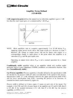
5 It canthus be used to monitor fault conditions causing high VSWR, or to align the load device for lowVSWR. A coupler used in this manner is called a leveling Application is illustrated coupler is connected between a signal generator and a load, such that the coupled portsamples power coming from the generator. It can thus monitor generator output independent ofload conditions. The coupled-port signal can be used to level the generator output. Sincegenerator output-power variation caused by load mismatch is suppressed by this feedbacktechnique, the generator- coupler combination will have a source VSWR which is much betterthan that of the generator if it were not Definition of Termscoupling coefficientThe ratio in dB of the incident power fed into the main port to the coupled port power when allports are terminated by reflection less toleranceThe allowable unit-to-unit variation in nominal flatnessThe maximum peak-to-peak variation in coupling coefficient that may be expected over aspecified frequency LossThe reduction in power available to the main-line output due solely to power transferred to thecoupled line.
6 It is equal to the theoretical minimum main-line insertion lossThe change in load power, due to the insertion of the coupler in a transmission system, withreflectionless terminations connected to the ports of the coupler . The main-line loss includes theeffect of power transferred to the coupled difference in dB of the power output at a coupled port, when power is transmitted in thedesired direction, to the power output at the same coupled port when the same amount of poweris transmitted in the opposite direction. In the case of a bi- Directional coupler , an alternativedefinition is the difference in dB of the power output of the two coupled ports, when power istransmitted in a constant direction on the main-line.
7 Reflectionless terminations are assumed tobe connected to all powerThe CW average power handling capability with one-way transmission through the main line ofthe coupler under matched load standing-wave ratio at any port of a coupler is specified for the case of reflectionlessterminations at all other ports. As with any device, VSWR is a measure of the quality of matchrelative to a given characteristic range of frequencies over which performance falls within specific couplerAnother name for a 4-port coupler ; that is, a single coupler having no internal termination. It isintended to allow forward and reflected signals to be sampled Directional couplerThe combination of two 3-port Couplers having their main lines cascaded, and their internallyterminated ports facing each other at the interface between the Couplers .
8 This providesbi- Directional coupler action, but with independent use of the coupled ports: A mismatched loadapplied to either of them will not affect the Often Asked Questions AboutDirectional CouplersQ. What is the difference between a 3-port and a 4-port coupler ?A. A Directional coupler is basically a 4-port network. The main-line and auxiliary line eachhave 2 ports: A 3-port coupler has one end of this auxiliary line, the "isolated port," internallyterminated. When all 4 ports are made available to the user, the device is called a "bi-directionalcoupler."Q. What advantage does a 3-port coupler have over a 4-port?
9 A. Directivity of a coupler is strongly affected by the impedance match provided by thetermination at the isolated port. Furnishing that termination internally ensures Can a 4-port coupler be used to sample forward and reflected power simultaneously, byplacing measuring instruments at both ports of the coupled line?A. Yes, but with care to provide good impedance match at all 4 ports of such a "bi-directionalcoupler." A coupler 's directivity can be no better than the return loss of the terminations at thefar-end main-line and coupled line ports; poor directivity causes inaccurate power monitoringby leaking forward and reflected signals into one another's paths.
10 An alternative approach whichovercomes this limitation is to use two 3-port Couplers back-to-back; this combination is calleda "dual Directional coupler ."Q. Is a coupled port an input or an output?A. It can be used as either. The coupling factor determines the attenuation between main-lineand coupled line signals in both How is directivity measured when the 4th port is internally terminated?A. Measure the loss from the main-line input to the coupled port with the main-line outputterminated. Then reverse the main-line connections. The difference in dB readings is How good does the directivity of a coupler have to be, as a reflectometer, to measure thereturn loss of an unknown impedance?