Transcription of Application Note - Spectron
1 Application Note SP5000 and AU6000 Series Dual Axis Tilt Sensor Mounting and Operation Guidelines Spectron GLASS AND ELECTRONICS INC. 595 OLD WILLETS PATH HAUPPAUGE NY 11788 PHONE: 631 582-5600 FAX: 631 582-5671 Specifications are subject to change without notice! Doc.# SAN-205-1004 MOUNTING The SP5000 and AU600 Series of Dual Axis Tilt Sensors were designed for PC board installation. The flat molded glass base is perpendicular to the internal contact pins within degrees, and should be used as the zero reference of the sensor. Following are recommended guidelines for hand soldering the dual axis 5-pin sensors. Solder gun set at 400-450 degrees.
2 Use Kester Rosin Core, no clean solder, # SN63PB37 for best results. Use Kester low residue solder flux #958 Following are recommended guidelines when tinning of the pins is desired. Have solder pot set at approximately 265 degrees .C. (using Kester solder #SN63PB37) Dip lead/pins in Kester flux # 2331. Immerse in solder pot for 2-3 seconds. Clean flux residue off with water. The SP5000 and AU6000 Series is also compatible with wave soldering at 260 CO for 10 seconds. ELECTRICAL CHARACTERISTICS The sensors are partially filled with a conductive fluid that will be degraded if any DC current is applied. Therefore, only AC excitation voltages may be used. These sensors will perform well using a simple Wheatstone Bridge Circuit, when following these recommendations.
3 Requires AC excitation A frequency of between 500 to 5 KHz A maximum amplitude of 5 volts peak to peak A square wave or sine wave is acceptable Tantalum capacitors are acceptable for decoupling the excitation signal When the excitation voltage is applied to the outer electrodes, and a phase sensitive voltmeter is hooked up between the center, and one of the excitation electrodes, it has an output proportional to the tilt angle. The output is zero volts if the sensor is aligned with the vertical plane. Any deviation from the alignment increases the output voltage. The tilt direction can be deduced from the phase between the excitation and center electrodes. The phase switches from 0 to 180 . The output impedance for the excitation should be lower than 10 ohms while the input impedance, which is tied to the center electrode, should be higher than 5 Meg ohms.
4 NOTE: There must not be any DC current applied to the sensor!!!! SIGNAL CONDITIONING Spectron offers the SA40011 and the CMOS based SA40015 signal conditioner which not only excites the sensor with a symmetrical AC wave form, but it is also insensitive to the large impedance changes between the operating temperature extremes. The SA40015 provides the user with a DC voltage output which can be interfaced to a display or an analog to digital converter. Since this series of dual axis sensors have a common neutral contact for both axes, it is necessary to either scan each axis individually using a sample and hold technique, or, as in the SA40015 signal conditioner, energize each axis with a different frequency which allows for a continuous output from each axis.
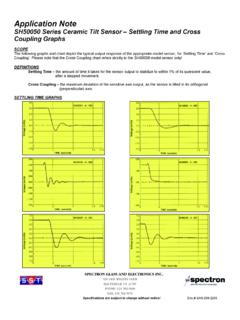
5 THERMAL CONSIDERATIONS If the sensor is exposed to thermal gradients in your Application , care should be taken to shield the glass body using either a heat sink type sleeve such as aluminum, or an insulated cover such as a Styrofoam cap. This will minimize the effect of unsymmetrical temperature distribution on the inside walls of the glass vial which would result in either an oscillating output or a constant drift depending on the type of electrolyte used and the delta T. DYNAMIC RESPONSE By changing the viscosity of the electrolyte, the sensors settling time can be varied from 200ms without any overshoot, to 500ms with an attenuation 7 times the final output signal, when a step input is introduced.