Transcription of Application of Model Based System Engineering (MBSE ...
1 Application of Model Based System Engineering (MBSE) Principles to an Automotive Driveline Sub- System ArchitecturePresented By: Robert Kraus, George Papaioannou and Arun SivanDiscussion Agenda Introduction & Project Summary Driveline Definitions and Concepts Systems Engineering Concepts MBSE Concepts Driveline Model Structure - Functional and Logical Decomposition Requirements & Test Case Management Requirements Management : Satisfy Relationships Parametric Relationships - Constraint Modeling Applied to Sizing Benefits of Applied MBSE2 Introduction & Project SummaryCurrent State: Today s automotive driveline System Engineering process is document Based Complex System requirements and specifications are communicated through large amounts of electronic data Often leads to incomplete or conflicting requirements Inefficient, redundant, error prone Running changes introduce potential problemsProject Summary: Obtained and deconstructed existing driveline System methods and sizing tools Identified need for improved requirements traceability in driveline systems Engineering Created detailed driveline System Model to apply the concepts of MBSE using SysML Added parametric constraints for sizing calculations Delivered functional MBSE Model as proof of concept3 Driveline Definitions and ConceptsArchitecture.
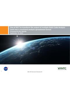
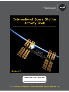
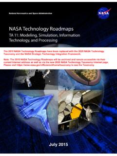
2 A driveline System links the powertrain output to the drive wheels Primary function is to transmit drive torque from the powertrain to the ground (wheels) Driveline subtypes such as FWD, RWD, AWD are treated as generalizations in SysMLComponents: Driveshaft / half shaft - transmits torque to front/rear or left/right Axle - multiplies driveshaft torque and directs to wheels Additional - Transfer case, PTU, disconnect device, U-joints, CV-joints, flex couplerSizing: Design optimization of each component, System and subsystem is the primary objective A sizing tool converts input data into torque outputs for all vehicle variations and uses industry standard equations and some correction factors. Complete AWD Driveline4 System Engineering Concepts V- Model : Top level requirements are decomposed to the subsystem and component levels, each with a specific validation plan flowing down the left side of the V and back up the right side.
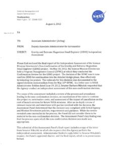
3 Context Diagram: Represents System interactions to an external environment Interacting systems are defined as black boxes P-Diagram: Expands and refines context for more detailed black boxes Includes detail on input signals, control factors, noise factors, outputs, and potential failure modes MBSE Modeling Language (SysML, UML etc) Modeling Method Modeling Tool (Magicdraw, IBM Rational Rhapsody etc)5V- ModelContext DiagramP-Diagram Requirements define customer and stakeholder needs in technical terms In SysML, System requirement statements are defined as objects Each object contains the requirement text & a unique identifier The requirement type defines the features a requirement can be associated with Generalizations manage and allocate requirements through inheritance relationships Requirements must be verified by test cases Test cases are checkpoints, such as design reviews or physical testsModel Based System Engineering Concepts.
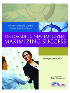
4 System Requirements6 Standard type requirements within SysML are used to provide rigor and clarity when defining the System Functions define what actions / activities must be accomplished or completed to achieve a desired outcome An operation is a property of a block A block is an abstract representation of any part of a System , like physical hardware or a signal Functions are linked through logical relationships to the various subsystems and components The logical architecture describes how a System will be implemented It abstractly defines a technical solution Based on the System s required sub-systems, components and their relationships A logical architecture should only be created after the System s functions and requirements are clearly defined It does not define any particular System implementation, but rather the general guidelines so as to remain solution-neutralModel Based System Engineering Concepts: Functional & Logical Architecture7 Methods of Modeling: Functional Decomposition Five basic operations of the driveline systems were identified from the P-diagram The System needs to Transmit torque Direct torque left / right Direct torque fore / aft Multiply torque Disconnect the secondary driveline Each function is associated, or mapped, to at least one logical block The function, or operation, is then inherited through generalizations8 Methods of Modeling.
5 Functional Decomposition Transmission of propulsion force from the powertrain to the wheels is the most basic, and most obvious, driveline function At the functional level of abstraction the degree or amount of torque transferred is not necessarily relevant all that matters is that all drivelines transmit torque In our Model the transmit torque function is inherited by all mechanical sub-systems and components It is important to note that no one component alone delivers or satisfies the transmit torque function - it is an emergent function of the total System The next function is to direct torque left/right which is the operation or behavior of a axle/transaxle differential logical block The next function is to direct torque fore-aft which is the behavior of a transfer case and is only present in AWD or 4X4 driveline configuration In a driveline System Model .
6 The multiply torque function is a behavior of the axle only The last function is the disconnect function which is the behavior of a disconnect device9 Methods of Modeling: Logical Decomposition Logical blocks are constructed after the functional blocks are defined, requiring some experience and Engineering judgement A good logical decomposition should remain untethered to any specific design concept, since it is unlikely that the first design concept will be the best design concept The driveline logical diagram provides the structure required to capture the vehicle inputs required to support parametric equations for calculating driveline impact torques, which is the basis for sizing10 Requirements & Test Case Management Import the requirements using the import feature in MagicDraw into a requirements package. Existing test methods are imported using a method similar to that of importing requirements Verify matrices are created and each requirement is verified by one or more test methods.
7 11 Requirement Management: Satisfy Relationships Requirements are satisfied by physical elements In MBSE this relationship is created at the logical level of abstraction, prior to any physical parts being designed The satisfy matrix indicates that each requirement is mapped to at least one logical block through a satisfy relationship that indicates that the logical block is required to deliver or meet the requirement The table shows all the logical elements in the driveline Model that satisfy requirements, and the requirements are separated into the seven different SysML requirement types12I think I am done for now. Will revise a bit more after Bob and Mike Relationships In systems Engineering , design involves making decisions between solution alternatives General process is: Generate ideas Evaluate alternatives - Engineering analysis Decide between alternatives - interpret results SysML provides a language to express and perform mathematical System analysis through parametric diagrams Parametric diagrams show mathematical relationships between the blocks of the System Model .
8 They act as constraints on the System Relationships: Sizing Inputs Parametric input parameters are obtained from industry standard equations for sizing (sizing tool). Mapping of parametric inputs as value properties associated with logical blocks Based on the property s logical ownership are shown here The impact torque sizing inputs are the value properties associated with the appropriate logical blocks At logical architecture levels, these value properties are to be defined variables that are not associated with any specific instance Specific instances can be created when required14 Parametric Relationships: Constraint modeling Parametric constraints specify equivalence relationships between logical blocks Defined in a similar manner to IBDs, but they use internal relationships with constraint parameters instead of part parameters Restricted to connecting only through binding connectors, typically with a parametric constraint at one end of the connection The key element is the constraint block, which is used to constrain the properties of one or more other blocks Constraint blocks consist of constraint expressions { = F * d } and constraint parameters (such as , F and d)15 Parametric Relationships: Driveline Sizing Goal.
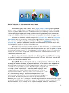
9 Show proof of concept for the calculation of sizing torques A total of eight different constraint blocks used to Model impact torque, consisting of torque flow equations, logic flow and Boolean assignments Instances need to be created with specific inputs to complete parametric analysis for driveline sizing Parametric calculations for impact torque were completed for a proposed vehicle program, and compared to the values obtained from existing analytical tools Successful proof of concept, however, requires more time and work to reliably replace existing analytical tool16 Benefits of Applied MBSE Object oriented modeling can be equally applicable to a fully mechanical System MBSE improves Engineering productivity and efficiency System models are more flexible, consistent and scalable across all sub-systems Streamlined communication of requirements by making all key input and output parameters available to all Model users Better traceability and linkages between requirements and their methods of verification The reduction of requirement redundancies and automatic validation of test case verification could result in the elimination of entire tracking departments The ability to continuously update and manage component design inputs through parametric relationships with vehicle level inputs Every individual with access to the Model can not only see and verify his or her subsystem.
10 But also view all of the interactions of their subsystem with other parts of the entire System minimizing cross functional issues and miscommunication17 Benefits of Applied MBSE We emphasized careful categorization of existing requirements and during the import process eliminated redundancies, reduced 500+ to ``~300 Through our integration efforts into SysML categories, we discovered a clear need and benefit of improved elicitation and partitioning of existing requirements Requirements and test cases can be added to the Model fairly easily, and can be easily linked with the entire driveline System . A new requirement with the document Based approach will require a lot of cross referencing with other requirements, and redundancies and total misses are quite possible18 Benefits of Applied MBSE: Parametric Input Cascade and Control Through parametric relationships, top level assumption changes are immediately cascaded down and can be verified against existing component variable properties For example, If engine torque in first gear goes up, it will immediately be calculated into transmission output torque and compared against the axle maximum input torque limit.