Transcription of APPLICATIONS Nissan Murano 2003-2007 99 …
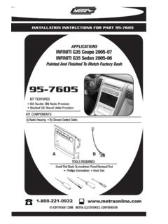
1 APPLICATIONSMETRA. The World s best kits. COPYRIGHT 2018 METRA ELECTRONICS CORPORATION REV. 5/5/2018 INST99-7612 CAUTION: Metra recommends disconnecting the negative battery terminal before beginning any installation. All accessories, switches, and especially air bag indicator lights must be plugged in before reconnecting the battery or cycling the : Refer to the instructions included with the aftermarket INSTRUCTIONS FOR PART 99-7612 PATENT # D719,560 ISO DIN radio provision with pocket ISO DDIN radio provision 7612A-Coated with brushed aluminum look 7612B-Painted matte black A) Radio housing B) Radio housing brackets C) Pocket D) (14) #8 x 3/8 Phillips screws E) (2) #8 x 1/2 Phillips screws F) 7612 Wire harnessKIT FEATURESKIT COMPONENTSWIRING & ANTENNA CONNECTIONS (sold separately)Wiring Harness: 70-7550 - 1995-up Nissan 70-7551 - 1995-up Nissan amp integrationAntenna Adapter.
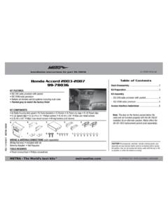
2 40-NI11 - Nissan Panel removal tool Phillips screwdriver Socket wrenchTOOLS REQUIREDN issan Murano 2003 -200799-7612A, 99-7612 BABCDEFDash Disassembly Nissan Murano 2003 - 2007 (without OE NAV)* ..2-3*Note: This kit will work in NAV models, but you will lose the OE NAV controls, and voice Assembly ISO DIN radio provision with pocket ..3-4 ISO DDIN radio provision ..4-5 Wiring Instructions ..599-7612 1. Unclip and remove the vent panel above the radio. (Figure A)2. Remove (2) Phillips screws exposed behind the vent panel. (Figure B)3. Unclip and remove the lower trim panel around the bottom of the radio panel. (Figure C)Dash Disassembly(Figure A)(Figure E)(Figure B)(Figure F)(Figure C)(Figure D)24. Remove (2) Phillips screws on each side of the radio chassis exposed behind the lower trim panel. (Figure D)5. Remove radio/climate control assembly from the sub Remove (4) Phillips screws securing the radio chassis to the factory radio trim panel.
3 Lift up slightly and proceed to step 7. (Figure E)7. Unlock the connector on the switch panel and remove the cable joining the chassis and switch panel. (Figure F) Continued on next pageLeft sideRight side99-7612 Dash DisassemblyKit Assembly(Figure B)(Figure A)(Figure C)(Figure G)(Figure H)ISO DIN radio provision with pocket1. Trim the shaded areas from the factory radio trim panel. (Figure A) Do not cut the locator and screw hole off as they will be necessary to mount the 99-7612 radio housing. (See detail)2. Attach the 99-7612 radio housing to the radio trim panel using (4) supplied 3/8 Phillips screws. (Figure B)3. Mount the radio housing brackets to the aftermarket radio with the screws supplied with the radio. (Figure C)4. Mount the pocket to the radio/bracket assembly using (4) 3/8 Phillips screws supplied with the kit. (Figure C) Continued on next page38. Remove the climate module from radio chassis assembly.
4 (Figure G) Note: The climate module will be reused in kit Remove (1) Phillip screw, securing the white flat 16-pin connector to the switch panel, then remove the connector. Note: This connector will be reused in kit Remove (8) Phillips screws securing the switch panel to the radio trim panel. (Figure H) Note: The radio trim panel will be reused in kit assembly. Continue to kit assemblyTrim shaded areasDetail99-7612 ISO DIN radio provision with pocket (continued)5. Mount the climate module to the radio/bracket assembly using (2) 3/8 Phillips screws supplied with the kit. (Figure D)6. Plug the white flat 16-pin connector, removed in disassembly, into the Mount the radio/pocket/climate assembly to the radio trim panel using (4) 3/8 Phillips screws supplied with the kit. (Figure E)8. Locate the factory wiring harness and antenna plug in the dash. Metra recommends using the proper mating adapters from Metra and/or AXXESS.
5 9. Follow the wiring instructions in this manual and reassemble dash in reverse order of Assembly(Figure D)(Figure E)4 ISO DDIN radio provision1. Trim the shaded areas from the factory radio trim panel. (Figure A) Do not cut the locator and screw hole off as they will be necessary to mount the 99-7612 radio housing. (See detail)2. Attach the 99-7612 radio housing to the radio trim panel using (4) supplied 3/8 Phillips screws. (Figure B)(Figure B)(Figure A)(Figure C)Trim shaded areasDetail3. Slide the ISO DDIN aftermarket radio into the radio housing brackets and secure with screws supplied with the radio. (Figure C) Continued on next page99-7612 ISO DDIN radio provision (continued)4. Mount the climate module to the radio/bracket assembly using (2) 3/8 Phillips screws supplied with the kit. (Figure D)5. Plug the white flat 16-pin connector, removed in disassembly, into the Mount the radio/climate assembly to the radio trim panel using (4) 3/8 Phillips screws supplied with the kit.
6 (Figure E)7. Locate the factory wiring harness in the dash. Metra recommends using the proper mating adapter from Metra or AXXESS. Re-connect the negative battery terminal and test the radio for proper Follow the wiring instructions in this manual and reassemble dash in reverse order of AssemblyWiring Instructions5 From the included 7612 harness:1. Plug the Black 16-way connector into the Plug the Black 12-way connector into the Plug the White 16-way connector into the factory Information Center Button Control Note:The Metra kit button layout does not provide the MAINT or the E/M buttons from the factory setup. MAINT button on the 99-7612 is accessed by pressing the DAY/NIGHT and HOUR buttons simultaneously. The E/M button is done by pressing PREV and MIN simultaneously.(Figure D)(Figure E) Additional 12-pin harness (ASWC-1) This 12-pin harness is to be used in conjunction with the ASWC-1 (not included).
7 Please refer to the ASWC-1 instructions for Notes99-7612 NotesMETRA. The World s best kits. COPYRIGHT 2018 METRA ELECTRONICS CORPORATIONREV. 5/5/2018 INST99-7612 KNOWLEDGE IS POWERE nhance your installation and fabrication skills by enrolling in the most recognized and respected mobile electronics school in our onto or call 800-354-6782 for more information and take steps toward a better tomorrow. Metra recommends MECP certified techniciansINSTALLATION INSTRUCTIONS FOR PART 99-7612 5/5/2018 INST99-7612 PRECAUCI N: Metra recomienda desconectar el terminal negativo de la bater a antes de comenzar cualquier instalaci n. Todos los accesorios, interruptores y, especialmente, las luces indicadoras de airbag deben estar enchufados antes de volver a conectar la bater a o comenzar el ciclo de ignici : Rem tase a las instrucciones incluidas con el radio de DE INSTALACI N PARA LA PIEZA 99-7612 METRA.
8 The World s best kits. COPYRIGHT 2018 METRA ELECTRONICS CORPORATION PATENT # D719,560 Provisi n de radio DIN ISO con bolsillo Provisi n de radio ISO DDIN 7612A - Recubierto con aspecto de aluminio cepillado 7612B - Negro mate pintado A) Carcasa del radio B) Soportes de carcasa del radio C) Cavidad D) (14) tornillos Phillips #8 x 3/8 E) (2) tornillos #8 x 1/2 F) Arn s de cables 7612 CARACTER STICAS DEL KITCOMPONENTES DEL KITCABLEADO Y CONEXIONES DE ANTENA (se venden por separado)Arn s de cableado: 70-7550 - Nissan 1995 y m s 70-7551 - Nissan 1995 y m s con integraci n de ampAdaptador de antena: Adaptador de antena Nissan 40-NI10 Herramienta para quitar paneles Destornillador Phillips Llave para dadosHERRAMIENTAS REQUERIDASN issan Murano 2003 -200799-7612A, 99-7612 BABCDEFD esmontaje del tablero Nissan Murano 2003 - 2007 (sin OE NAV)* ..2-3*Nota: Este kit funciona en algunos modelos de navegaci n, pero se perder n los controles OE NAV, y los mensajes de del kit Provisi n de radio DIN ISO con bolsillo.
9 3-4 Provisi n de radio ISO DDIN ..4-5 Instrucciones de cableado ..599-7612 1. Desenganche y quite el panel de moldura que rodea la pantalla, incluyendo los controles del aire acondicionado. (Figura A)2. Quite los (2) tornillos Phillips que quedan a la vista detr s de la rejilla/panel de moldura de la pantalla. (Figura B)3. Desenganche y quite el panel de moldura de abajo alrededor de la parte de abajo del panel del radio. (Figura C)Desmontaje del tablero(Figura A)(Figura E)(Figura B)(Figura F)(Figura C)(Figura D)24. Quite los (2) tornillos Phillips de cada lado del chas s del radio que quedan a la vista detr s del panel de la moldura de abajo. (Figura D)5. Quite el ensamble del radio/control de clima del sub Quite los (4) tornillos Phillips que sujetan el chas s del radio al panel de la moldura del radio de f brica. (Figura E)7. Desbloquee el conector del panel del interruptor y quite el cable que une el chas s y el panel del interruptor.
10 (Figura F) Contin a en la p gina siguientelado izquierdolado derecha99-7612 Desmontaje del tableroEnsamble del kit(Figura B)(Figura A)(Figura C)(Figura G)(Figura H)Provisi n de radio DIN ISO con bolsillo1. Recorte las reas sombreadas del panel de la moldura del radio de f brica. (Figura A) No corte el localizador y el tornillo hueco off, ya que ser necesario para montar la carcasa de la radio 99-7612. (Ver detalle)2. Una la carcasa del radio 99-7612 al panel de la moldura del radio usando los (4) tornillos Phillips de 3/8 incluidos. (Figura B)3. Monte los soportes de la carcasa del radio en la unidad central con los tornillos incluidos con la unidad. (Figura C)4. Monte el bolsillo en el ensamble del radio/soporte usando los (4) tornillos Phillips de 3/8 incluidos. (Figura C) Contin a en la p gina siguiente38. Retire el m dulo clim tico del conjunto del chasis del radio. (Figura G) Nota: El m dulo de clima se volver a utilizar en el montaje del Retire (1) Phillip tornillo, asegurando el plano conector de 16 pines de color blanco a el panel de interruptores, a continuaci n, retire el conector.