Transcription of APPLIED THERMODYNAMICS TUTORIAL 2 GAS COMPRESSORS
1 1 APPLIED THERMODYNAMICS TUTORIAL 2 GAS COMPRESSORS In order to complete this TUTORIAL you should be familiar with gas laws and polytropic gas processes. You will study the principles of reciprocating COMPRESSORS in detail and some principles of rotary COMPRESSORS . On completion you should be able to the following. Describe the working principles of reciprocating COMPRESSORS . Define and calculate swept volume. Define and calculate volumetric efficiency. Define and calculate isothermal efficiency. Define and calculate indicated power. Dtate the benefits of cooling. Calculate the heat rejected through cooling. Define and calculate the interstage pressures for multiple COMPRESSORS . Define polytropic efficiency.
2 Let s start by considering the general use of compressed air. 2 1. COMPRESSED AIR TYPES Air is an expansive substance and dangerous when used at high pressures. For this reason, most applications are confined to things requiring low pressures (10 bar or lower) but there are industrial uses for high pressure air up to 100 bar. The common source of the air is the compressor . There are many types of COMPRESSORS with different working principles and working conditions. These are examples. Reciprocating. Sliding vane COMPRESSORS . Lobe COMPRESSORS . Helical screws. Centrifugal. Axial turbine COMPRESSORS . The function of all of them is to draw in air from the atmosphere and produce air at pressures substantially higher.
3 Usually a storage vessel or receiver is used with the compressor . The same principles are APPLIED to the compression of other gasses. This TUTORIAL is mainly about reciprocating COMPRESSORS . The other types are covered briefly. The reciprocating compressor is probably the most versatile of all the types and is only out performed by rotary types when large volumes at low pressures are required. For high pressures, the reciprocating compressor is almost universal. ATMOSPHERIC VAPOUR Air and vapour mixtures are covered in detail in a later TUTORIAL . We should note, however, the effects it has on the performance of an air compressor . Atmospheric air contains WATER VAPOUR mixed with the other gases.
4 When the air is cooled to the dew point, the vapour condenses into water and we see rain or fog. The ratio of the mass of water vapour in the air to the mass of the air is called the ABSOLUTE HUMIDITY. The quantity of water that can be absorbed into the air at a given pressure depends upon the temperature. The hotter the air, the more water it can evaporate. When the air contains the maximum possible amount of vapour it is at its dew point and rain or fog will appear. The air is then said to have 100% humidity. When the air contains no water vapour at all (dry air), it has 0% humidity. This refers to RELATIVE HUMIDITY. For example if the air has 40% humidity it means that it contains 40% of the maximum that it could contain.
5 There are various ways to determine the humidity of air and instruments for doing this are called HYGROMETERS. The importance of humidity to air COMPRESSORS is as follows. When air is sucked into the compressor , it brings with it water vapour. When the air is compressed the pressure and the temperature of the air goes up and the result is that the compressed air will have a relative humidity of about 100% and it will be warm. When the air leaves the compressor it will cool down and the water vapour will condense. Water will then clog the compressor , the receiver and the pipes. 3 Water causes damage to air tools, ruins paint sprays and corrodes pipes and equipment.
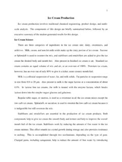
6 For this reason the water must be removed and the best way is to use a well designed compressor installation and distribution network. TYPICAL compressor LAYOUT The diagram below shows the layout of a two stage reciprocating compressor typically for supplying a workshop. Figure 1 1. Induction box and silencer on outside of building with course screen. 2. Induction filter. 3. Low pressure stage. 4. Intercooler. 5. High pressure stage. 6. Silencer. 7. Drain trap. 8. After cooler 9. Pressure gauge. 10. Air receiver. 11. Safety pressure relief valve. 12. Stop valve FREE AIR DELIVERY When a gas such as air flows in a pipe, the mass of the air depends upon the pressure and temperature.
7 It would be meaningless to talk about the volume of the air unless the pressure and temperature are considered. For this reason the volume of air is usually stated as FREE AIR DELIVERY or FAD. FAD refers to the volume the air would have if let out of the pipe and returned to atmospheric pressure at the same temperature. The FAD is the volume of air drawn into a compressor from the atmosphere. After compression and cooling the air is returned to the original temperature but it is at a higher pressure. Suppose atmospheric conditions are paTa and Va (the FAD) and the compressed conditions are p, V and T. 4 Applying the gas law we have ..DAFTppVTVTVpTpVaaaaaa=== 2.
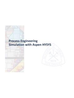
8 CYCLE FOR RECIPROCATING compressor THEORETICAL CYCLE The diagram shows the basic design of a reciprocating compressor . The piston reciprocates drawing in gas, compressing it and expelling it when the pressure inside the cylinder reaches the same level as the pressure in the delivery pipe. Figure 2 If the piston expels all the air and there is no restriction at the valves, the pressure - volume cycle is as shown below. Figure 3 Gas is induced from 4 to 1 at the inlet pressure. It is then trapped inside the cylinder and compressed according the law pVn = C. At point 2 the pressure reaches the same level as that in the delivery pipe and the outlet valve pops open. Air is then expelled at the delivery pressure.
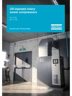
9 The delivery pressure might rise very slightly during expulsion if the gas is being compacted into a fixed storage volume. This is how pressure builds up from switch on. 5 VOLUMETRIC EFFICIENCY In reality, the piston cannot expel all the gas and a clearance volume is needed between the piston and the cylinder head. This means that a small volume of compressed gas is trapped in the cylinder at point 3. When the piston moves away from the cylinder head, the compressed gas expands by the law pVn = C until the pressure falls to the level of the inlet pressure. At point 4 the inlet valve opens and gas is drawn in. The volume drawn in from 4 to 1 is smaller than the swept volume because of this expansion.
10 Figure 4 The volumetric efficiency is defined as vol=Induced VolumeSwept Volume This efficiency is made worse if leaks occur past the valves or piston. The clearance ratio is defined as c = Clearance volume/Swept volume. Ideally the process 2 to 3 and 4 to 1 are isothermal. That is to say, there is no temperature change during induction and expulsion. 6 WORKED EXAMPLE Gas is compressed in a reciprocating compressor from 1 bar to 6 bar. The FAD is 13 dm3/s. The clearance ratio is The expansion part of the cycle follows the law pV = C. The crank speed is 360 rev/min. Calculate the swept volume and the volumetric efficiency. SOLUTION Swept Volume = V Clearance volume = V Consider the expansion from 3 to 4 on the p-V diagram.