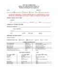
Transcription of APPROVAL IN PRINCIPLE - Westminster City Council
1 WCC TA Ref /B15719/TA_16137 PW BD 2 / 12 May 2012 Perm works to Eurocodes rev 7 Page 1 of 26 APPROVAL IN PRINCIPLE (Permanent works design) Name/ Address of Project 17 South Eaton Place, Belgravia, London SW1W 9ER Type or Structure basement vault alteration involving lowering of floor slab + Underpinning and new structural floor slab (Permanent works) - Dwelling with Grade II Listed Status Structure Ref No. 1. HIGHWAY DETAILS Type of highway London local distributor road networks Permitted traffic speed 48 km/h (30 mph) Existing restriction * To lists whether environmental, width, weight, no parking, bollards, other barriers, double yellow lines or height restriction is present in the vicinity of the property or construction site.
2 2. SITE DETAILS & EXISTING STRUCTURE Description of existing structure / sub-structures layout/configuration: type of foundations, retaining walls, masonry arches, construction type in relation to the highway boundaries and any obstacles crossed. Provide reasons for alteration/repairs/strengthening. 3. PROPOSED STRUCTURE Description of structure and design working life * To provide a general description of the proposed structure or sub-structures development or redevelopment including the overall dimensions, - length, width and depth in relation to the highway.
3 The design working life of the structure, including temporary structure, and replaceable structural parts to be given. They should be expressed as a number of years. Structural type * To provide dimensional details (thickness, height, sizes, grades of concrete or steel) of proposed structural components. To take into consideration of the slenderness ratios of supporting elements that provides stability to the structures or sub-structures. Foundation type * To provide information relating to proposed foundation (including diameter of piles, or sizes for driven pile type, total length, embedment depth and the types of piles construction or raft foundation).
4 For replacement type piles, provide information about the extent of the reinforcement. Span arrangements WCC TA Ref /B15719/TA_16137 PW BD 2 / 12 May 2012 Perm works to Eurocodes rev 7 Page 2 of 26 * To specify the span arrangements/configuration of proposed structural elements including horizontal, vertical and or inclined components. Articulation arrangements * To specify proposed fixities types at the supports, connections or joints (either as built-in, sliding, free, pin or restraint in one or two directions). To indicate the proposed fixity in the idealized force diagram as per section Proposed classes/levels Consequences class * (Refer to BS EN 1990:2002+A1:2005 Table B1) Reliability class * (Refer to BS EN 1990:2002+A1:2005 Table B2) Inspection level * (Refer to BS EN 1990:2002+A1:2005 Table B5) Road restraint systems requirements Proposed arrangements for future maintenance and inspection Traffic management Arrangements for future maintenance and inspection of structure.
5 Access arrangements for structure Environment and Sustainability issues considered. Materials and finishes Durability. Material and finishes * For concrete structures, give applicable exposure classes for particular structural elements. For all material strengths given, list the relevant codes/standards Risks and hazards considered for design, execution, maintenance and demolition. Consultation with and /or agreement from Principal Designer. * Designer to name the Principal Designer (PD) and to append an endorsed statement from PD confirming that the risks and hazards identified in the AIP permanent works design proposal are appropriate and compliance with the latest CDM Regulations 2015.
6 Estimated cost of proposed structure together with other structural forms considered and the reasons for their rejection including comparative whole life costs with dates of estimates Proposed arrangements for construction Construction of structure Traffic management Service diversions Interface with existing structures WCC TA Ref /B15719/TA_16137 PW BD 2 / 12 May 2012 Perm works to Eurocodes rev 7 Page 3 of 26 4. DESIGN CRITERIA Actions (to specify design load safety factors to ULS where applicable) Permanent Actions (axial & lateral loadings) * To specify respective loadings and associate design safety factors @ ULS Snow, wind and thermal actions Actions relating to normal traffic under Authorized Weight (AW) Regulations 1998 and Construction & Use (C&U) Regulations 1996 Actions relating to General Order Traffic under Special Types General Order (STGO)
7 Regulations 2003 Footway or footbridge variable actions Actions relating to Special Order Traffic, provision for exceptional abnormal indivisible loads including location of vehicle track on deck cross-section Accidental actions Actions during construction Any special action not covered above ( seismic action, atmospheric icing, floating debris etc) Heavy or high load route requirements and arrangements being made to preserve the route, including any provision for future heavier loads or future widening Minimum headroom provided (including allowance for vertical sag compensation and maximum deflection of structures).
8 Standards and documents List of relevant documents from the Technical APPROVAL Schedule (TAS) * (To strike out those standards that are not relevant with the design but need to incorporate BD 2/12) Refer to Annex B1 Mandatory CDM Regulations 2015 BD 2/12 Technical APPROVAL of Highway Structures Additional relevant Standards and publications Proposed Departures relating to departures from standards given in (If applicable, provide reasons or supporting documents) WCC TA Ref /B15719/TA_16137 PW BD 2 / 12 May 2012 Perm works to Eurocodes rev 7 Page 4 of 26 Proposed Departures relating to methods for dealing with aspects not covered by standards and documents in 5 STRUCTURAL ANALYSIS To provide design philosophy approach and methods of analysis proposed for superstructure, sub-structure and foundations.
9 * Lists the main structural elements for superstructure, sub-structure and foundation. * If the designs of the superstructure, sub-structure and /or foundation are to be implemented by an independent Organization Design Team / Sub-Consultant, the Main Structural Designer must provide and specify all relevant loading conditions, constraints and external actions to be taken into account. The conditions and actions must be covered in the AIP. * This will define the respective designers responsibilities in association with the different sub-structures proposal.
10 * (Notes: Calculations sheets are NOT required with the submission) Description and diagram of idealised structure to be used for analysis - Diagram should: Indicate nodes are fixed or pinned Illustrate support points and direction of restraints Illustrate external loading To provide force diagrams (triangular and rectangular shapes representing the relevant applied loadings to the structural elements) To indicate type of restraints at the supports Assumptions intended for calculation of structural element stiffness To provide characteristic properties of proposed structural elements Proposed range of soil parameter to be used in the design of earth retaining elements and sub-structures associate with the foundation.


