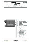
Transcription of APT10-PPU, APT14-PPU and APT14HC-PPU (Closed System ...
1 Local regulations may restrict the use of this product to below the conditions quoted. In the interests of development and improvement of the product, we reserve the right to change the specification without notice. Copyright 2014. TI-P680-01. ST Issue 2. APT10-PPU, APT14-PPU and APT14HC-PPU ( closed System ). Automatic Pump-trap packaged Units Description The Spirax Sarco APT10-PPU, APT14-PPU and APT14HC-PPU automatic pump-trap packaged units are plug in systems specifically designed to remove condensate from plant under 'stall' conditions. The whole System is capable of handling capacities up to 2 800 kg / h pumping and 9 000 kg / h trapping, depending on available differential pressure. Each unit comes with a condensate receiver, motive supply drain trap and ancillaries. Operated by steam the APT10, APT14 and APT14HC-PPU 's meet a wide range of applications. The standard pump-trap is manufactured from SG iron, although electroless nickel plated (ENP) versions are available on request.
2 Standards These products fully comply with the requirements of the European Pressure Equipment Directive 97 / 23 / EC and carry the mark. All welding is in accordance with ASME IX, BS EN 287 / 288, BS EN part 1-2004 and BS EN ISO 15614 part 1-2004. Certification These products are available with a Declaration of Conformity. Other certification is available for individual component parts if required, at extra cost. Note: All certification / inspection requirements must be stated at the time of order placement. W X. Y. Z. Sizes and pipe connections W2 W1. Connects to Connects to W X Y Z the System flange W of Condensate Motive Exhaust / Condensate pipework the unit Unit size inlet supply balance outlet line Spool piece DN20 x DN20. APT10-PPU PN16 DN65 DN15 DN15 DN20. ( " x "). DN40 x DN25. APT14-PPU PN16 DN100 DN15 DN15 DN25. (1 " x 1"). DN50 x DN40. APT14HC-PPU PN16 DN125 DN15 DN15 DN40.
3 (2" x 1 "). Optional extras A spool piece is available to connect the receiver to the System pipework. Page 1 of 3. Limiting conditions APT10 PN10. Unit design conditions APT14 and apt14hc PN16. APT10 bar g Maximum motive inlet pressure (steam). APT14 and apt14hc bar g APT10 bar g Maximum operating pressure APT14 and apt14hc bar g APT10 4 bar g Maximum backpressure APT14 and apt14hc 5 bar g APT10 155 C. Maximum operating temperature APT14 and apt14hc 198 C. Minimum operating temperature 0 C. APT10 15 bar g Designed for a maximum cold hydraulic test pressure of: APT14 and apt14hc 24 bar g Note: For operating temperatures above or below those stated contact Spirax Sarco. Capacities Sizing of the pump-trap is dependent on motive pressure, backpressure *. (lift, return System pressure and frictional losses) and process conditions. 10. For accurate sizing for the application please contact Spirax Sarco.
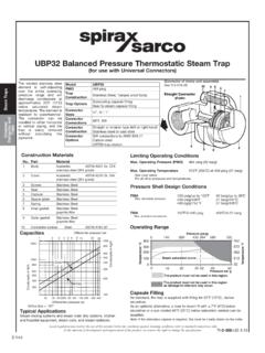
4 1 2. 12. 4. 5 9. 4. 2 11. 8. 6. Items 9, 10, 11 and 12 are to be connected to the outlet of the System by the end user . 7 3. Materials No. Part Material 1 Receiver Carbon steel 2 Ball valves DN20 to DN50 ( " to 2") Steel (PTFE seals). 3 Trap set DN15 ( ") Stainless steel (PTFE seals) 4 Strainer DN15 to DN50 ( " to 2") SG iron 5 Pump - trap SG iron 6 Diffuser Stainless steel 7 Base and supporting frame Carbon steel 8 Name - plate Aluminium *9 Air vent Stainless steel PC10HP / UBP32. *10 Check valve Stainless steel *11 Ball valve DN15 ( ") Stainless steel *12 Air eliminator Austenitic stainless steel AE50S. * Please note: Items 9, 10, 11 and 12 are not included with the pump package. They must be ordered as a separate item. It is intended that the end user provides the pipework and connects these components correctly - see Section 3 'Installation' of the Installation and Maintenance Instructions (IM-P680-02) supplied with the unit.
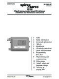
5 TI-P680-01 ST Issue 2 APT10-PPU, APT14-PPU and APT14HC-PPU ( closed System ) Page 2 of 3. Automatic Pump-trap packaged Units APT - Dimensions / weights (approximate) in mm and kg Unit size A B C D E F G H I J K L M N Weight DN20 x DN20 ( " x ") 642 428 228 1024 1081 588 600 549 428 110 253 795 375 - 110. DN40 x DN25 (1 " x 1") 657 528 353 1064 1081 723 600 547 400 285 320 755 282 244 170. DN50 x DN40 (2" x 1 ") 743 553 353 1215 1081 787 600 618 425 250 400 833 322 253 220. L. K M N. Flow W. Flow A. H. B. I. C. E J. D G. F. Spool piece - Dimensions (approximate) in mm Unit size W1 W2 O P. DN25 173 20 W2 O W1. DN20 x DN20 DN65 DN40 176 13 Connects to the Connects to System pipework flange W of the DN50 180 7 Spool piece unit DN40 196 31. C. DN40 x DN25 DN100. DN50 201 26 Face W2 P C. Face W1. DN65 199 19. DN80 204 12. DN50 227 41. DN65 227 33. DN50 x DN40 DN125. DN80 232 24.
6 DN100 234 13. Safety information, Installation and maintenance For full details see the Installation and Maintenance Instructions supplied with the unit. For full details of the individual component products see separate Installation and Maintenance Instructions also supplied with the unit. Spare parts Either refer to the individual component product Technical Information sheets (TI) or Installation and Maintenance Instructions (IM) supplied with the unit, for availability of spare parts. How to specify Spirax Sarco APT14-PPU (APT10 - PPU or apt14hc - PPU) closed System automatic pump-trap packaged unit, operated by steam up to bar g ( bar g for the APT10 - PPU). The complete System shall be supplied with PED markings, with all welding in accordance with BS EN 287 / 288. How to order example 1 off Spirax Sarco DN40 x DN25 APT14-PPU ( closed System ) automatic pump-trap packaged unit with flanged PN16 external connections plus the optional DN100 x DN40 spool piece.
7 +. 1 off Spirax Sarco air vent kit for APT14-PPU . TI-P680-01 ST Issue 2 APT10-PPU, APT14-PPU and APT14HC-PPU ( closed System ) Page 3 of 3. Automatic Pump-trap packaged Units