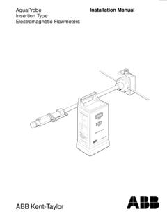
Transcription of AquaMaster™ Installation Manual - Controls …
1 AquaMaster Installation instruction that draws attention to the risk ofinjury or instruction that draws attention to the risk ofdamage to the product, process or of an instruction or reference for more detailed informationor technical of InstructionsAlthough Warninghazards are related to personal injury, and Cautionhazards are associated with equipment orproperty damage, it must be understood that operation of damaged equipment could, under certain operational con-ditions, result in degraded process system performance leading to personal injury or death. Therefore, comply fullywith all Warningand in this Manual is intended only to assist our customers in the efficient operation of our equipment.
2 Useof this Manual for any other purpose is specifically prohibited and its contents are not to be reproduced in full or partwithout prior approval of the Marketing Communications and SafetyTo ensure that our products are safe and without risk to health, the following points must be noted:1. The relevant sections of these instructions must be read carefully before Warning labels on containers and packages must be Installation , operation, maintenance and servicing must only be carried out by suitably trained personneland in accordance with the information Normal safety precautions must be taken to avoid the possibility of an accident occurring when operatingin conditions of high pressure and/or Chemicals must be stored away from heat.
3 Protected from temperature extremes and powders kept safe handling procedures must be When disposing of chemicals ensure that no two chemicals are advice concerning the use of the equipment described in this Manual or any relevant hazard datasheets (where applicable) may be obtained from the Company address on the back cover, together withservicing and parts information. 2002 ABB Water Meters. All rights !!!! Installation and maintenance must only becarried out by suitably trained relevant sections of this Manual mustbe read before selecting a requirements of this equipment,any associated equipment and the localenvironment must be taken Installation and use of this equipmentmust be in accordance with relevantnational and local.
4 12 MECHANICAL Installation .. Unpacking .. Installation Conditions .. Mechancial Installation .. 43 ELECTRICAL Installation .. Grounding .. Connections .. Terminal BoxConnections(Remote Versions only) .. Protection .. Connections .. Input/Output Connections .. Outputs .. Interface .. Connector Input/OutputConnections (Option) .. Connector Input/Output(Option) - AquaMag x10 Pulse Output Compatibility .. Output(Option) .. ComputerConnection .. 13 ComputerConnection .. Supply Connection .. Transducer(Optional) .. Protection .. 16 4 START-UP AND OPERATION .. Connecting Batteries.
5 Start-up .. Display Activation .. Replacing a Battery .. Kits .. Changing Procedures .. 21 APPENDIX - AQUAMASTER BLOCKDIAGRAM .. 231 INTRODUCTIONAquaMaster includes the family of high performanceelectromagnetic flow meters for water measurement thatnormally are supplied as factory configured, calibrated MECHANICAL INSTALLATIONFig. Installation NOT exceed themaximum working pressure marked onthe SpillageFig. VibrationFig. Localized HeatFig. SitingAllow room toread displayFig. Straight Pipe Requirements> > DirectionFig. Fluid LevelFig. Within Temperature Limits140 F (Maximum60 C)AquaMaster-4 F -20 C()MinimumFig.
6 Shade22 MECHANICAL Mechanical Transmitter DimensionsTransmitter Mounting PlateAquaMasterAquaMaster TransmitterInstallation and wiringaccess 12" minimum,18" preferredAllowance for cable bend - each side6" (Standard)9" (Armored) "( ) "( ) "(13mm) (155mm) (140mm)7(176mm) "(146mm) "(125mm) "(170mm) "(150mm)43 ELECTRICAL INSTALLATION3 ELECTRICAL (Figs. to )Fig. PipelineswithCathodic ProtectionSupplied BondingCablesGasketGasketSupplied Bonding CableGrounding RingCaution. Do NOT groundCathodically Protected this end of themeter to the pipeline(using groundingring if required)Insulating Sleeveand Washer(not provided)Insulated connectingwire (not included).
7 Must be adequatelyrated to carrycathodic 5/8" to 1" threaded endsensors will require a plastic isolationsection in the pipe, and a cathodiccurrent bypass Terminal Box Connections (Remote Versions Only)Fig. Potting the Terminal BoxWarning.!!!!!!Potting materials are toxic use suitablesafety the manufacturer s instructions carefullybefore preparing the potting remote sensor terminal box connectionsmust be potted immediately on completion toprevent the ingress of all connections before potting seeELECTRICAL not overfill or allow the potting material tocome into contact with O rings or not let potting material enter conduit, (Remote Versions Only)3 ELECTRICAL INSTALLATION83 ELECTRICAL Input/Output Outputs - Fig.
8 Interface - Fig. ELECTRICAL connector Input/Output connections (Option) - Fig. ELECTRICAL Connector Input/Output (Option) - AquaMag x10 Pulse Ouput CompatibilityWhere an existing Installation has been wired to operate from the x10 outputs of an AquaMag , the wiring of theAquaMaster connector can be altered to suit, as shown in Fig. Ouput (Standard Option AquaMaster Only) - Fig. ELECTRICAL Computer Connection - Fig. Local Computer Connections ABB Part to 9-pinSerial Data socket onPDA or PC via'Laplink' lead/adaptor9-pin female(direct to PC)AquaMaster TransmitterOriginal StyleCurrent Style133 ELECTRICAL Computer Connection - Fig.
9 ELECTRICAL Supply connection - Fig. or AC/Battery Powered UnitsBattery Powered Units3 ELECTRICAL Transducer (Optional AquaMaster S only)Optional pressure transducer cables are available for a range of pressures and cable TransducerConnectorFig. AquaMaster fitted with OptionalPressureTransducer ConnectorCaution. Ensure that only thepressure transducer supplied with thetransmitter is of other pressure transducers willrequire alteration of the pressure spanand zero factors in the transmitter see Quick Reference Environmental Protection - Sensor Potting16 Fig. Remove lid from If fitted, note position of batteries and then remove frombattery ELECTRICAL Remove battery tray by pushing right-most clips towards the left and lifting4.
10 Check to insure that all required cables are fitted correct-ly and that either a connector, gland or blanking plug seals all gland Carefully pour potting into termination area, until potting just covers the terminal prevent possibility of short circuit, potting compound should cover all terminal screw Re-insert battery tray. Gently press down on the battery tray so that the potting level Leave to stand for 15 minutes to allow potting to If present, refit batteries to original positions and refit START-UP AND OPERATION4 START-UP AND Connecting BatteriesThe AquaMaster has been supplied with one or two batteries, but not connected.