Transcription of ARCE 302-Structural Analysis - web.calpoly.edu
1 ARCE 302-Structural Analysis Lecture Notes, Fall 2009 Ansgar Neuenhofer Associate Professor, Department of Architectural Engineering California Polytechnic State University, San Luis Obispo Copyright 2009 Ansgar Neuenhofer (photo by author) TABLE OF CONTENTS 1 Review of Statics 1 Goal of structural Analysis 1 structural idealizations 1 Summary of properties of moment and shear force diagrams 2 Example 3 Frames 6 Example 9 Statical determinacy-Instability-Degree of indetermincay 10 Problems 14 2 Principal of Virtual Forces 18 Introductory remarks 18 Virtual work-Principle of virtual
2 Forces 18 Procedure for Analysis 19 Principle of virtual forces for trusses 19 Principle of virtual forces for beams 19 Principle of virtual forces for frames 19 Example 20 Example 22 Integration tables 23 Summary 25 Example 27 Example 28 Example 20 Example 32 Shear deformation 35 Problems 38 3 The Force Method 49 Introduction 49 Discussion 49 Example 50 Example 53 Example (Alternative)
3 55 Example 57 Example 60 Force method for arbitrary degree of statical indeterminacy 64 Maxwell's law 64 Summary of force method 65 Example 65 Example 70 Example 73 The force method for space frames 75 Problems 78 4 The Slope-Deflection Method 88 General remarks 88 End moments for prismatic members 89 Example 93 Example 95 Example 97 Example 99 Summary of procedure 102 Comparison between slope-deflection and force methods 103 Fixed-end moments 104 Problems 106 5 The Moment-Distribution Method 113 Introduction 113 General
4 Description 113 Example 114 Example 116 Summary of steps 118 More discussion and illustration 119 Example 120 Summary 122 Problems 123 6 Approximate Analysis of building frames under lateral load 126 Introduction 126 Discussion 126 The Portal Method 128 The Cantilever Method 133 Problems 143 7 Influence Lines 145 Introduction 145 M ller-Breslau principle 148 Use of influence lines 149 Example 150 Properties of influence lines of statically determinate structures 151 Influence lines of statically indeterminate structures 152 Problems 156 11 Review of Statics Goal of structural Analysis The objective of a structural Analysis is to determine the force (stress) and displacement (strain)
5 Demand of structures using a mechanical model. The Analysis must be both as economical as possible and as accurate as necessary. Since the exact mechanical relations are extremely complicated, we rely on many approximations that are more or less accu-rate. With these approximations and simplifications we map the real structure onto our mechanical model. It is impor-tant that we are aware of these simplifications in order to judge whether or not certain models are appropriate. After se-lecting an appropriate structural model, we analyze the model under the most unfavorable combination of loads. The results of structural Analysis are the internal forces and deformations that form the basis for, say, reinforced concrete, steel or timber design.
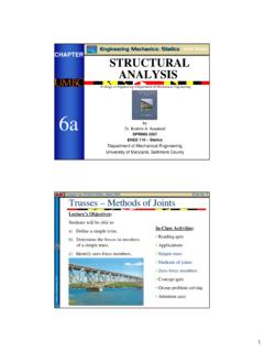
6 We have to always remember that the results of any structural Analysis can never be better than the underlying model. A crude model remains a crude model and yields crude results, no matter how many digits we include in our Analysis , in short garbage in-garbage out. In this class we talk little about modeling but assume that we already have an appropriate mechanical representation of the real structure. Thus we are omitting a very important step of en-gineering work, if not the most important, a fact we should always be aware of. structural idealizations All structures are three-dimensional. In structural Analysis we usually work with one- or two-dimensional idealizations of the real structure.
7 (a) 3-dimensional structural elements (rarely used in structural engineering) (b) 2-dimensional structural elements (plate, shells) (c) 1-dimensional structural elements structural elements whose two dimensions (width and height) are small compared to their length are commonly called truss (axial force response) or beam (bending moment response) elements. In this class, we often use the term frame member or frame element to denote a combination of truss and beam elements. We represent a frame element by its axis, which is the connection of the centroids of the cross-sections. In this class, we will be dealing with one-dimensional structural elements (truss, beam and frame members) only.
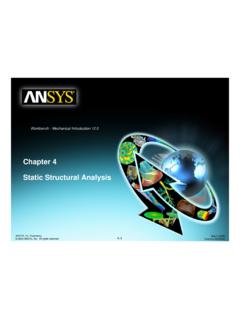
8 We use those to model plane (two-dimensional) structures and, to a smaller extent, space (three-dimensio-nal) structures. xyHLHL requirement yLxLH Summary of Properties of Moment and Shear Force Diagrams In the following, we summarize key properties of shear force and bending moment diagrams. In beam segments without distributed loading, the shear force is constant and the bending moment is linearly varying. In regions with a uniformly distributed load the shear force varies linearly and the bending moment is a qua-dratic parabola. In general, if the distributed load is of ordern, the functions for the shear force and bending moment are of order1n+ and2n+, respectively.
9 At points where a concentrated force (a reaction force or an externally applied force) is applied the shear force is discontinuous. It jumps upward or downward according to the direction of the force. The moment func-tion has a change in slope at that point but is continuous. An external moment causes a jump in the bending moment. It does not change the slope of the moment func-tion, nor does it affect the shear force at that location. The shear force is the derivative of the bending moment. Hence the moment function is one degree higher than the shear force function. When the shear force is zero, the bending moment takes on its maximum.
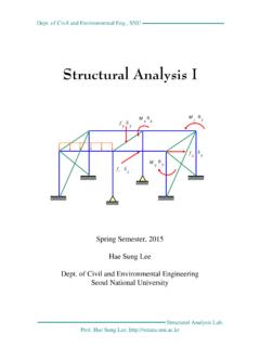
10 Fig. Properties of shear force and bending moment diagrams. yAyB+ wLPVwPLMABLM+linearquadraticlinearlinear linearchange in slopeno change in slopeno change in slopeLMmaxM0V= Example : Beam with internal hinges Fig. Beam with internal hinges. Problem: Draw the bending moment and shear force diagrams for the beam in Fig. Shown in Figure is a beam with two internal hinges. The first important observation is that this structure is not a single rigid body. If we remove the beam from its supports, it ceases to be rigid. We can easily see, that we can rotate against because of the hinge. The consequence for calculating the support reactions is that we have to break the struc-ture apart and look at free-body diagram of individual parts.