Transcription of Architectural Blueprints The 4+1 View Model of Software ...
1 Paper published in IEEE Software 12 (6). November 1995, pp. 42-50. Architectural Blueprints The 4+1 View Model of Software Architecture Philippe Kruchten Rational Software Corp. Abstract This article presents a Model for describing the architecture of Software -intensive systems, based on the use of multiple, concurrent views. This use of multiple views allows to address separately the concerns of the various stakeholders' of the architecture: end-user, developers, systems engineers, project managers, etc.
2 , and to handle separately the functional and non functional requirements. Each of the five views is described, together with a notation to capture it. The views are designed using an architecture-centered, scenario- driven, iterative development process. Keywords: Software architecture, view, object-oriented design, Software development process Introduction We all have seen many books and articles where one diagram attempts to capture the gist of the architecture of a system. But looking carefully at the set of boxes and arrows shown on these diagrams, it becomes clear that their authors have struggled hard to represent more on one blueprint than it can actually express.
3 Are the boxes representing running programs? Or chunks of source code? Or physical computers? Or merely logical groupings of functionality? Are the arrows representing compilation dependencies? Or control flows? Or data flows? Usually it is a bit of everything. Does an architecture need a single Architectural style? Sometimes the architecture of the Software suffers scars from a system design that went too far into prematurely partitioning the Software , or from an over-emphasis on one aspect of Software development: data engineering, or run-time efficiency, or development strategy and team organization.
4 Often also the architecture does not address the concerns of all its customers (or stakeholders as they are called at USC). This problem has been noted by several authors: Garlan & Shaw1, Abowd & Allen at CMU, Clements at the SEI. As a remedy, we propose to organize the description of a Software architecture using several concurrent views, each one addressing one specific set of concerns. An Architectural Model Software architecture deals with the design and implementation of the high-level structure of the Software .
5 It is the result of assembling a certain number of Architectural elements in some well-chosen forms to satisfy the major functionality and performance requirements of the system, as well as some other, non-functional requirements such as reliability, scalability, portability, and availability. Perry and Wolfe put it very nicely in this formula2, modified by Boehm: Software architecture = {Elements, Forms, Rationale/Constraints}. Software architecture deals with abstraction, with decomposition and composition, with style and esthetics.
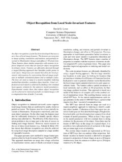
6 To describe a Software architecture, we use a Model composed of multiple views or perspectives. In order to eventually address large and challenging architectures, the Model we propose is made up of five main views (cf. fig. 1): The logical view, which is the object Model of the design (when an object-oriented design method is used), the process view, which captures the concurrency and synchronization aspects of the design, the physical view, which describes the mapping(s) of the Software onto the hardware and reflects its distributed aspect, the development view, which describes the static organization of the Software in its development environment.
7 The description of an architecture the decisions made can be organized around these four views, and then illustrated by a few selected use cases, or scenarios which become a fifth view. The architecture is in fact partially evolved from these scenarios as we will see later. End-user Programmers Functionality Software management Development Logical View View Scenarios Process View Physical View Integrators System engineers Performance Topology Scalability Communications Figure 1 The 4+1 view Model We apply Perry & Wolf's equation independently on each view, , for each view we define the set of elements to use (components, containers, and connectors)
8 , we capture the forms and patterns that work, and we capture the rationale and constraints, connecting the architecture to some of the requirements. Each view is described by a blueprint using its own particular notation. For each view also, the architects can pick a certain Architectural style, hence allowing the coexistence of multiple styles in one system. We will now look in turn at each of the five views, giving for each its purpose: which concerns is addresses, a notation for the corresponding Architectural blueprint, the tools we have used to describe and manage it.
9 Small examples are drawn from the design of a PABX, derived from our work at Alcatel Business System and an Air Traffic control system3, but in very simplified form the intent here is just to give a flavor of the views and their notation and not to define the architecture of those systems. The 4+1 view Model is rather generic : other notations and tools can be used, other design methods can be used, especially for the and the logical and process decompositions, but we have indicated the ones we have used with success.
10 2. The Logical Architecture The Object-Oriented Decomposition The logical architecture primarily supports the functional requirements what the system should provide in terms of services to its users. The system is decomposed into a set of key abstractions, taken (mostly) from the problem domain, in the form of objects or object classes. They exploit the principles of abstraction, encapsulation, and inheritance. This decomposition is not only for the sake of functional analysis, but also serves to identify common mechanisms and design elements across the various parts of the system.