Transcription of Architectural Hydronic Wall Fin - Trane Heating & Air ...
1 ArchitecturalHydronic Wall FinFIN-PRC004-ENOctober 2001 2001 American Standard Inc. All rights Complete Line of Wall FinTrane Architectural wall fin is ideal forheating modern commercial,institutional or industrial styling and wide applicationflexibility allow wall fin cabinet designsto be used for virtually any for Hydronic or steam Heating , Trane wall fin can also be used incombination with convectors for smallerareas, allowing for the use of one sourcewhen designing a radiation heatingsystem. (See FIN-DS-2 for convectorapplications.)An effective Heating system for any office.
2 Attractive styling that blends with anyarchitectural Wall Fin Simply the BestWall fin effectively meets the heatingneeds of long, open areas. It counterscold air downdrafts common toexpansive glass areas used in many oftoday s most prestigious buildings. Provides continuous heat along roomperimeter. Allows removal of any unit panel forservice accessibility. The front panel never touches the wall only Trane s exclusive mountingstrip. The front panel can be raised orremoved without disturbing the unit ordamaging wallpaper, paint or theplaster seal. Operates quietly because there are nomoving parts.
3 Controls with the damper or valveindividually. Blends well with any decor. Works effectively with cooling-onlyVAV and heat recovery systems. Includes 14 or 16-gauge front panels. Unit vent draft barrier enclosures. Pipe enclosures for use with ForceFloand Fan Coil FinI=B=R Certified Ratings for Trane WallFinThe I=B=R symbol is the registeredtrademark of the Hydronics Institutewhich tests and rates in strict accordancewith published standard wall finelements and elements with wall fin Heating units must conformto appropriate test standards to havecertified I=B=R Hydronics?Besides the reliability of equipmentratings, and the well establishedreliability of Hydronic accessories, thereare many good reasons why hydronicsystems have long been recognized asthe standard method for providingindoor Heating , whether steam or hotwater, provides positive, controlledcirculation of the Heating are basically self-balancing, andin larger, more complicated heatingsystems, balancing is positivelycontrolled by familiar valves life of some Hydronic equipmentmay be measured in decades; someexisting boilers are more than fifty yearsold.
4 In addition to the high efficiency ofboilers (some over 85%) the lossesthrough the distribution system areextremely low on modern control is close to ideal withhydronics. Any well-designed systemcan provide excellent comfort, withoutdrafts or sharp swings in flexibility of Hydronic installationspermits a variety of pipingarrangements, simple or sophisticatedcontrols, and a large choice of roomdistribution units for all TType TAType FType SFeaturesand Benefits3 ContentsFIN-PRC004-ENArchitecural Wall FinFeatures and BenefitsApplication ConsiderationsSelection ProcedurePerformance DataDimensional DataOptionsMechanical SpecificationsSecurity Wall FinFeatures and BenefitsAccessoriesModel Number DescriptionPerformance and General DataDimensional DataMechanical SpecificationsHydronic Light CommercialSlope Top Wall Fin Model 11 SFeatures and BenefitsPerformance and General DataDimensional DataCover and Accessory LayoutMechanical
5 Specifications74757677859126714415456939 698100101 FIN-PRC004-EN4 Features andBenefitsA simple installation designed to lastwithout visible fasteners Trane sexclusively designed mounting stripmakes it strip keys entireinstallation, attaches to anywall, and assures the tightestfit possible even againstthe most imperfect fulllength ofmountingstrip foreasy steelenclosurebracketsprovideelementsupp ort baseand brace theEnd PanelElement/pipesupportsposition in slotsin the enclosurebracket to allowtwo-tierelement and nylon cradleguides assure exact elementlocation and allow elementcradles to slide freely rectangularmetal washers toassure tight fit againstthe as wallpanel as plasterstop for front panels hingeinvisibly into the mounting element damperprovides clip slides over panel lip to hold itsecurely to clip
6 And slide bolt fastener for frontpanel alignment are hidden from unit with extruded grille. The grille isseparate and hinges into the mounting andBenefitsHydronic Heating Elements Copper/Aluminum and SteelCopper-Aluminum Elements 3/4 , 1 and 1 1/4 (19 mm, 25 mm and 32mm) Copper Tubes With 40, 50 or 58 Aluminum Fins per foot (131, 164 190per meter).Positive Temperature Control Efficient element-mounted damper. Reduces unit capacity by 70 percent. Has jam-proof bead chain controlsystem. Control knob is mounted on the 1/4 (32 mm)3/4 (19 mm)1 (25 mm)Steel Elements Standard optionsfeature 1 1/4 (32 mm) steel tube with 52steel fins per foot (171 per meter).
7 Elements available in copper-aluminum or steel. Elements are efficient and long lasting. Element tubes mechanically expandedinto fin collars. Fin collars provide even and positivespacing for even air distribution. The mechanical bond assures anefficient and durable elementassembly. Fins cannot work Models S, F, T & TA1 1/4 (32 mm)FIN-PRC004-EN6 ApplicationConsiderationsA Heating System and Style to Suit Any ApplicationWall MountedFront OutletSlope TopOutletTop OutletFSTTATop OutletWithExtrudedGrilleType EType XEnclosure styles meet the Heating needsof long, open areas in any interior.
8 Wall-mounted wall fin enclosuresavailable in depths of four and sixinches (102 mm, 152 mm). Enclosure depth is determined by thetype of element to be used. See pages 13 through 43 and Tables PD-1 through PD-25 for details. Front inlet grilles. Bottom inlet grilles. Inverted enclosures for styles S, F andT enclosures only. Tamperproof fastener option. Pipe EnclosuresWall Mounted Cabinet Options4 1/2 (114 mm)ContinuousSheet MetalAngle3 3/8 (86 mm)Pipe EnclosureBottom Inlet GrilleInverted EnclosureFront Inlet GrilleTamperproofFastenerCeiling MountedType CS1/2 (13 mm) Dia. Mtg. Hole Ceiling-mounted wall fin enclosuresavailable in depths of four and sixinches (102 and 105 mm).
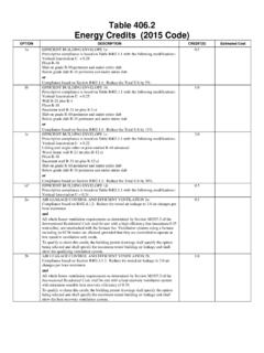
9 See pages 13, 14, 15 and MountedType E3 Type E3-2 WType E3A-1 WType E3A-2W Pedestal wall fin enclosures availablewith one or two wide elements. See pages 36, 37, 42, 53, 54, 55, 56, 57and 58 and Tables PD-24, PD-25, M-1, M-2, M-3, M-4 and Wall FinSelectionHot Water SystemsThe capacity rating of wall fin in a hotwater Heating system depends on thedifference between average watertemperature and entering airtemperature, and on the velocity atwhich water is circulated through thetube. The effect of water velocity on thecapacity rating is appreciable (see ChartS-1) and should be taken into accountwhen selecting wall fin.
10 Following areexample selections for hot Water SystemsExample 1 Assume a two-pipe system is being usedwith 180 F average water temperature,20 F temperature drop and 65 F enteringair temperature. Assume a calculatedheat loss of 20,000 Btu, for which onerow of 1 1/4 steel element in a Type 12 Senclosure is Chart S-1, reading from 20,000 Btu(under 20 F temperature drop) across toa 1 1/4 steel element and down, indicatesa water velocity of approximately .45 ft/sec. The water velocity correction factorcorresponding to .45 ft/sec is .920. Theradiation is selected so that it woulddeliver20,000 Btu (calculated heat loss) (velocity correction factor)or 21,739 Btu if the water velocity were 3ft/sec.