Transcription of Arduino Starter Kit Grove-Starter Kit - Seeed Studio
1 Grove-Starter Kit Arduino Starter Kit . About Grove-Starter Kit For someone first dabbling in the world of Arduino , the Grove-Starter Kit is an excellent choice in the journey of learning. This kit includes a variety of basic input and output modules and sensors. Using grove as a unified interface to connect each module, this kit can help you create interesting circuits without soldering. About this Tutorial To jazz the tutorial up a bit and make something fun in the process, we created a cute farmhouse out of small wooden dowels, added some adorable clay creatures, and strung some EL wire for flare. Then we integrated the modules from the grove Starter Kit to animate the environment and illustrate their practical applications. Packing List for the Grove-Starter Kit Copyright by Seeedstudio 1 grove -Base Shield Connectors - 10 grove Cables Functional modules: 1 grove -Buzzer 1 grove -LED 1 grove -Tilt Switch 1 grove -Rotary Angle 1 grove -Temperature 1 grove -Button Sensor Sensor 1 grove -Smart Relay 1 grove -Protoshield 1 grove -Serial LCD.
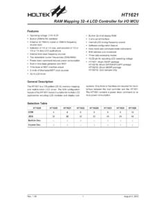
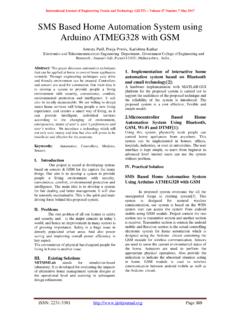
2 Preparation Base Shield Introduction Copyright by Seeedstudio The purpose of the Base Shield is to allow easy connection of any microprocessor input and output pins to grove units. Each socket is clearly labeled with its matching I/O pin and contains 5 V, GND, and two I/O pin connections. For a more detailed examination of the Base Shield please refer to the diagram below. Common digital IO. Common analog IO. Hardware Installation When using the digital I/O, note the staggered alignment of the pins that is, one socket handles D1 and D2, the next D2 and D3, and so on. If you are going to use a grove input module and a grove output module which have two signal pins, like the LED module and the button module, separate your grove cables so that a socket is between them as shown below.
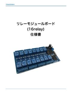
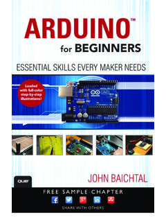
3 grove connectors for two-signal grove modules cannot sit side-by-side on the Base Shield, because one pin, such as D2, will be utilized by both modules simultaneously. On the other hand, if you have two grove units that use only one digital pin each, such as the tilt switch or the buzzer, they can sit alongside each Copyright by Seeedstudio other on the Base Shield as they only use one of the digital lines in the connecting cable and therefore will not interfere with each other. These rules apply to the Analog I/O sockets, as well. Make sure you know the layout of each socket before you hook up your connectors. Integratation with Arduino /Seeeduino Take out your Arduino or Seeeduino, and insert the pins of the Base Shield into the corresponding Arduino /Seeeduino ones, as depicted above.
4 Arduino Analog & Digital Pins Analog Pins: Arduino reads analog signals through analog pins, and outputs analog signals through pulse-width modulation (PWM). Arduino has 6 analog input ports (A0-A5). and 6 analog output ports (D3 D5 D6 D9 D10 D11). These pins can be used to supply variable output voltages. Pins (A0-A5) can also be used as digital input and output pins, but by default, they are analog input pins. Digital Pins: Arduino reads digital signals from digital pins. These pins can be used as both input and output pins. Arduino has 14 digital I/O pins (D0-D13), of which D13 is usually used as an output pin because it is connected to an LED on PCB. NB: All signals read from the pins are voltages instead of current values. Because of the high internal resistance in the pins, only a little current passes to the ground.
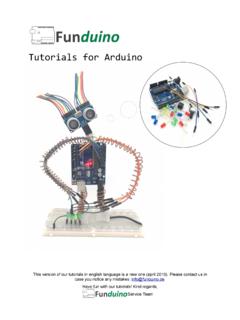
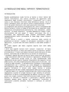
5 IDE Installation We won't give an introduction of this part here. For more detailed information, please refer to the website, , and then install step-by-step according to your operating system. Welcome to the Grove-Starter Kit Farmhouse Project Copyright by Seeedstudio 1. Doorbell Button + Buzzer Goal: When the doorbell/button is pushed, the buzzer will buzz and announce the visitor. Module Introduction Button: Simple momentary button for input. Buzzer: It can be connected to digital outputs, and will emit a tone when the output is high. Alternatively it can be connected to an analog pulse-width modulation output to generate various tones and effects. Hardware Setup Materials Needed: 1 Button + 1 Buzzer + 2 grove Cables Hardware Connection Method: Plug the button module into the D1 connector on the Base Shield.
6 The button is now connected to digital pin 1 on the Arduino . Plug the buzzer into the D2 connector on the Base Shield. Now the buzzer is connected to digital pin 2 on the Arduino . Software Design Code 1: Simple Doorbell int buttonPin = 1;. Copyright by Seeedstudio int buzzerPin = 2;. void setup(). {. pinMode(buttonPin,INPUT);//set button as digital input pinMode(buzzerPin,OUTPUT);//as buzzer as digital output }. void loop(). {. if(digitalRead(buttonPin))//check button is pressed or not {. digitalWrite(buzzerPin,HIGH);//pressed then buzzer buzzes }. else {. digitalWrite(buzzerPin, LOW);//not pressed then buzzer remains silent }. }. Ultimate Result Press the doorbell, and the buzzer will Buzz B . Code 2: Musical Doorbell int buttonPin = 1;. int buzzerPin = 2.
7 Int length = 40; // the number of notes char notes[] = "ccggaagffeeddc "; // a space represents a rest int beats[] = { 1,1,1,1,1,1,2,1,1,1,1,1,1,2,4 };. int tempo = 300;. void playTone(int tone, int duration) {. for (long i = 0; i < duration * 1000L; i += tone * 2) {. digitalWrite(buzzerPin, HIGH);. delayMicroseconds(tone);. digitalWrite(buzzerPin, LOW);. delayMicroseconds(tone);. }. }. void playNote(char note, int duration) {. char names[] = { 'c', 'd', 'e', 'f', 'g', 'a', 'b', 'C' };. int tones[] = { 1915, 1700, 1519, 1432, 1275, 1136, 1014, 956 };. // play the tone corresponding to the note name Copyright by Seeedstudio for (int i = 0; i < 8; i++) {. if (names[i] == note) {. playTone(tones[i], duration);. }. }. }. void setup() {. pinMode(buzzerPin, OUTPUT).}
8 PinMode(buttonPin,INPUT);. }. void loop() {. if(digitalRead(buttonPin)). {. for (int i = 0; i < length; i++) {. if (notes[i] == ' ') {. delay(beats[i] * tempo); // rest } else {. playNote(notes[i], beats[i] * tempo);. }. // pause between notes delay(tempo / 20);. }. }. }. End Result Press the doorbell, and the buzzer will play beautiful music. 2. Little Chandelier Rotary Angle Sensor Goal: Rotate the Rotary Angle Sensor and the luminance of the chandelier inside the house will increase or decrease depending on the rotary angles. Copyright by Seeedstudio Module Introduction Rotary Angle Sensor: It can be used as an Arduino /Seeeduino analog input. Its output voltage changes according to the rotated angles. LED: It can be used as an Arduino /Seeeduino digital output, or it can also be controlled using PWM.
9 Hardware Setup Materials Needed: 1 Rotary Angle Sensor + 3 LEDs + 4 grove Cables Hardware Connection Method: Plug the rotary angle sensor into the A0 connector on the Base Shield. The rotary angle sensor is now connected to analog pin 0 on the Arduino . Plug 3 LEDs into theD3, D4, D5 connectors on the Base Shield. The 3. LEDs are now connected to digital pins 3, 4, and 5 on the Arduino . Software Design Code: Little Chandelier int sensorPin = 0;. int ledPin1 = 3;. int ledPin2 = 4;. int ledPin3 = 5;. int sensorValue = 0;. void setup(). {. pinMode(ledPin1,OUTPUT);//set 3 LEDs as digital output pinMode(ledPin2,OUTPUT);. pinMode(ledPin3,OUTPUT);. }. void loop(){. sensorValue = analogRead(sensorPin);//read the value from the sensor //adjust the value 0 to 1024 to 0 to 255.}
10 SensorValue = map(sensorValue,0,1024,0,255);. analogWrite(ledPin1,sensorValue);//write the value Copyright by Seeedstudio analogWrite(ledPin2,sensorValue);. analogWrite(ledPin3,sensorValue);. }. 3. Swing Goal: When the bear swings, the green EL wire will light up.. Module Introduction . Tilt Switch: This is used as an ordinary switch. When it tilts, the switch is off; when it's balanced, the switch is on. Smart Relay: Control high voltage circuit by 5 V logic digital output. Relay is equal to an electronic switch. When the signal from the Arduino /Seeeduino is at a high level, the switch is off and vice versa. This switch can also be used in other circuits. In this case, relay is a switch in the luminescent tube circuit. Hardware Setup Materials Needed: 1 Tilt Switch + 1 Smart Relay + 2 grove Cables + 1 EL wire +.