Transcription of ARM Cortex-M4 32b MCU+FPU, 210DMIPS, up to 1MB …
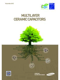
1 STM32F405xx STM32F407xx ARM Cortex-M4 32b MCU+FPU, 210 DMIPS, up to 1MB flash /192+4KB RAM, USB. OTG HS/FS, Ethernet, 17 TIMs, 3 ADCs, 15 comm. interfaces & camera Datasheet - production data IC/OC/PWM or pulse counter and quadrature FBGA. (incremental) encoder input Debug mode LQFP64 (10 10 mm) Serial wire debug (SWD) & JTAG. LQFP100 (14 14 mm). WLCSP90. UFBGA176 interfaces LQFP144 (20 20 mm) (10 10 mm). LQFP176 (24 24 mm) Cortex-M4 Embedded Trace Macrocell . Up to 140 I/O ports with interrupt capability Up to 136 fast I/Os up to 84 MHz Features Up to 138 5 V-tolerant I/Os Core: ARM 32-bit Cortex -M4 CPU with FPU, Up to 15 communication interfaces Adaptive real-time accelerator (ART Up to 3 I2C interfaces (SMBus/PMBus). Accelerator ) allowing 0-wait state execution Up to 4 USARTs/2 UARTs ( Mbit/s, ISO. from flash memory, frequency up to 168 MHz, 7816 interface, LIN, IrDA, modem control). memory protection unit, 210 DMIPS/. DMIPS/MHz (Dhrystone ), and DSP Up to 3 SPIs (42 Mbits/s), 2 with muxed instructions full-duplex I2S to achieve audio class accuracy via internal audio PLL or external Memories clock Up to 1 Mbyte of flash memory 2 CAN interfaces ( Active).
2 Up to 192+4 Kbytes of SRAM including 64- SDIO interface Kbyte of CCM (core coupled memory) data RAM Advanced connectivity Flexible static memory controller USB full-speed device/host/OTG. supporting Compact flash , SRAM, controller with on-chip PHY. PSRAM, NOR and nand memories USB high-speed/full-speed device/host/OTG controller with dedicated LCD parallel interface, 8080/6800 modes DMA, on-chip full-speed PHY and ULPI. Clock, reset and supply management 10/100 Ethernet MAC with dedicated DMA: V to V application supply and I/Os supports IEEE 1588v2 hardware, MII/RMII. POR, PDR, PVD and BOR 8- to 14-bit parallel camera interface up to 4-to-26 MHz crystal oscillator 54 Mbytes/s Internal 16 MHz factory-trimmed RC (1% True random number generator accuracy). CRC calculation unit 32 kHz oscillator for RTC with calibration Internal 32 kHz RC with calibration 96-bit unique ID. Low power RTC: subsecond accuracy, hardware calendar Sleep, Stop and Standby modes Table 1.
3 Device summary VBAT supply for RTC, 20 32 bit backup registers + optional 4 KB backup SRAM Reference Part number 3 12-bit, MSPS A/D converters: up to 24 STM32F405RG, STM32F405VG, STM32F405ZG, STM32F405xx channels and MSPS in triple interleaved STM32F405OG, STM32F405OE. mode STM32F407VG, STM32F407IG, STM32F407ZG, STM32F407xx 2 12-bit D/A converters STM32F407VE, STM32F407ZE, STM32F407IE. General-purpose DMA: 16-stream DMA. controller with FIFOs and burst support Up to 17 timers: up to twelve 16-bit and two 32- bit timers up to 168 MHz, each with up to 4. June 2013 DocID022152 Rev 4 1/185. This is information on a product in full production. 1. Contents STM32F405xx, STM32F407xx Contents 1 Introduction .. 11. 2 Description .. 12. Full compatibility throughout the family .. 15. Device overview .. 18. ARM Cortex -M4F core with embedded flash and SRAM .. 19. Adaptive real-time memory accelerator (ART Accelerator ) .. 19. Memory protection unit.
4 19. Embedded flash memory .. 19. CRC (cyclic redundancy check) calculation unit .. 20. Embedded SRAM .. 20. Multi-AHB bus matrix .. 20. DMA controller (DMA) .. 21. Flexible static memory controller (FSMC) .. 22. Nested vectored interrupt controller (NVIC) .. 22. External interrupt/event controller (EXTI) .. 22. Clocks and startup .. 22. Boot modes .. 23. Power supply schemes .. 23. Power supply supervisor .. 23. Voltage regulator .. 25. Regulator ON/OFF and internal reset ON/OFF availability .. 28. Real-time clock (RTC), backup SRAM and backup registers .. 28. Low-power modes .. 29. VBAT operation .. 30. Timers and watchdogs .. 30. Inter-integrated circuit interface (I C) .. 33. Universal synchronous/asynchronous receiver transmitters (USART) . 33. Serial peripheral interface (SPI) .. 34. Inter-integrated sound (I2S) .. 34. Audio PLL (PLLI2S) .. 34. Secure digital input/output interface (SDIO) .. 35. Ethernet MAC interface with dedicated DMA and IEEE 1588 support.
5 35. Controller area network (bxCAN) .. 36. 2/185 DocID022152 Rev 4. STM32F405xx, STM32F407xx Contents Universal serial bus on-the-go full-speed (OTG_FS) .. 36. Universal serial bus on-the-go high-speed (OTG_HS) .. 36. Digital camera interface (DCMI) .. 37. Random number generator (RNG) .. 37. General-purpose input/outputs (GPIOs) .. 37. Analog-to-digital converters (ADCs) .. 37. Temperature sensor .. 37. Digital-to-analog converter (DAC) .. 38. Serial wire JTAG debug port (SWJ-DP) .. 38. Embedded Trace Macrocell .. 38. 3 Pinouts and pin description .. 39. 4 Memory mapping .. 69. 5 Electrical characteristics .. 74. Parameter conditions .. 74. Minimum and maximum values .. 74. Typical values .. 74. Typical curves .. 74. Loading capacitor .. 74. Pin input voltage .. 74. Power supply scheme .. 75. Current consumption measurement .. 76. Absolute maximum ratings .. 76. Operating conditions .. 77. General operating conditions .. 77. VCAP_1/VCAP_2 external capacitor.
6 79. Operating conditions at power-up / power-down (regulator ON) .. 80. Operating conditions at power-up / power-down (regulator OFF) .. 80. Embedded reset and power control block characteristics .. 80. Supply current characteristics .. 82. Wakeup time from low-power mode .. 95. External clock source characteristics .. 96. Internal clock source characteristics .. 99. PLL characteristics .. 100. PLL spread spectrum clock generation (SSCG) characteristics .. 102. DocID022152 Rev 4 3/185. Contents STM32F405xx, STM32F407xx Memory characteristics .. 104. EMC characteristics .. 106. Absolute maximum ratings (electrical sensitivity) .. 108. I/O current injection characteristics .. 109. I/O port characteristics .. 109. NRST pin characteristics .. 113. TIM timer characteristics .. 114. Communications interfaces .. 116. 12-bit ADC characteristics .. 129. Temperature sensor characteristics .. 134. VBAT monitoring characteristics .. 134.
7 Embedded reference voltage .. 135. DAC electrical characteristics .. 135. FSMC characteristics .. 137. Camera interface (DCMI) timing specifications .. 155. SD/SDIO MMC card host interface (SDIO) characteristics .. 156. RTC characteristics .. 157. 6 Package characteristics .. 158. Package mechanical data .. 158. Thermal characteristics .. 169. 7 Part numbering .. 170. Appendix A Application block diagrams .. 171. USB OTG full speed (FS) interface solutions .. 171. USB OTG high speed (HS) interface solutions .. 173. Ethernet interface solutions.. 174. 8 Revision history .. 176. 4/185 DocID022152 Rev 4. STM32F405xx, STM32F407xx List of tables List of tables Table 1. Device summary .. 1. Table 2. STM32F405xx and STM32F407xx: features and peripheral counts.. 13. Table 3. Regulator ON/OFF and internal reset ON/OFF availability.. 28. Table 4. Timer feature comparison .. 30. Table 5. USART feature comparison .. 34. Table 6. Legend/abbreviations used in the pinout table.
8 44. Table 7. STM32F40x pin and ball definitions .. 45. Table 8. FSMC pin definition .. 57. Table 9. Alternate function mapping .. 60. Table 10. STM32F40x register boundary addresses .. 70. Table 11. Voltage characteristics .. 76. Table 12. Current characteristics .. 77. Table 13. Thermal characteristics.. 77. Table 14. General operating conditions .. 77. Table 15. Limitations depending on the operating power supply range .. 79. Table 16. VCAP_1/VCAP_2 operating conditions .. 80. Table 17. Operating conditions at power-up / power-down (regulator ON) .. 80. Table 18. Operating conditions at power-up / power-down (regulator OFF).. 80. Table 19. Embedded reset and power control block characteristics.. 81. Table 20. Typical and maximum current consumption in Run mode, code with data processing running from flash memory (ART accelerator enabled) or RAM .. 83. Table 21. Typical and maximum current consumption in Run mode, code with data processing running from flash memory (ART accelerator disabled).
9 84. Table 22. Typical and maximum current consumption in Sleep mode .. 87. Table 23. Typical and maximum current consumptions in Stop mode .. 88. Table 24. Typical and maximum current consumptions in Standby mode .. 88. Table 25. Typical and maximum current consumptions in VBAT mode.. 89. Table 26. Switching output I/O current consumption .. 92. Table 27. Peripheral current consumption .. 93. Table 28. Low-power mode wakeup timings .. 95. Table 29. High-speed external user clock characteristics.. 96. Table 30. Low-speed external user clock characteristics .. 96. Table 31. HSE 4-26 MHz oscillator characteristics .. 98. Table 32. LSE oscillator characteristics (fLSE = kHz) .. 99. Table 33. HSI oscillator characteristics .. 99. Table 34. LSI oscillator characteristics .. 100. Table 35. Main PLL characteristics.. 101. Table 36. PLLI2S (audio PLL) characteristics .. 101. Table 37. SSCG parameters constraint .. 102. Table 38. flash memory characteristics.
10 104. Table 39. flash memory programming .. 104. Table 40. flash memory programming with VPP .. 106. Table 41. flash memory endurance and data retention .. 106. Table 42. EMS characteristics .. 107. Table 43. EMI characteristics .. 108. Table 44. ESD absolute maximum ratings .. 108. Table 45. Electrical sensitivities .. 109. Table 46. I/O current injection susceptibility .. 109. DocID022152 Rev 4 5/185. List of tables STM32F405xx, STM32F407xx Table 47. I/O static characteristics .. 110. Table 48. Output voltage characteristics .. 111. Table 49. I/O AC characteristics .. 112. Table 50. NRST pin characteristics .. 114. Table 51. Characteristics of TIMx connected to the APB1 domain .. 115. Table 52. Characteristics of TIMx connected to the APB2 domain .. 116. Table 53. I2C characteristics.. 116. Table 54. SCL frequency (fPCLK1= 42 MHz.,VDD = V) .. 118. Table 55. SPI dynamic characteristics .. 118. Table 56. I2S dynamic characteristics.