Transcription of As Equipment Evolves, So Must Piping Practices … Split ...
1 American Standard Inc. 1998 Volume 27, No. 4 December 1998nproviding insights fortoday s HVAC system designerAs Equipment Evolves, So Must Piping Practices .. Split Systems And interconnecting refrigerant LinesThe efficiency and reliability of an R-22, Split air-conditioning system hinges largely on the Piping that connects the refrigerant -condensing and air-handling sides of the system . Operational difficulties are inevitable if this interconnecting Piping is improperly designed or installed, regardless of how carefully the Equipment was selected and Piping designs that successfully avoid these difficulties share several common traits:nA simple, direct layout that reduces the amount of system refrigerant tube size that consistently returns oil to the refrigerant tube size that doesn t cause excessive pressure drops which reduce compressor efficiency and of the Piping techniques discussed in this newsletter wouldn t have been considered good practice in the past, but they work best and most reliably for modern commercial Trane Equipment with scroll Engineers Newsletter previews the selection and refrigerant Piping guidelines now recommended for Trane s current line of commercial Split - system /scroll-compressor Equipment .
2 (Literature detailing these guidelines is slated for publication in 1999.) Equipment SelectionThe success of any HVAC application begins with choosing the right system and properly sizing the Equipment . If a Split air-conditioning system best suits the project, then observe these guidelines:nBase your selection on a minimum coil suction temperature of 40 F for constant-volume systems and 43 F for variable-air-volume (VAV) systems. These limits promote stable performance over the system s entire operating the system using design conditions and check for proper operation at the expected operating using hot gas bypass in comfort cooling applications. It squanders energy and is seldom necessary for properly designed systems. If coil-frosting is a concern, consider adding an evaporator defrost control such as Frostat coil frost PipingKeep these general guidelines in mind as you review the recommendations specific to suction, liquid, discharge and hot gas bypass lines:nLimit overall line length, including the vertical suction rise.
3 Pay particular attention to liquid risers. Enough subcooling may be lost as refrigerant travels up the riser to cause flashing. Review any questionable applications with the Type L copper tubing for R-22. For copper-to-copper joints, use BCuP-6 without flux. For copper-to-steel or copper-to-brass joints, use BAg-28 with a non-acid pipe sizing software such as Trane engineering toolbox to quickly determine proper sizes for refrigerant lines based on current engineering data. 'RXEOH ULVHUV DQGULVHU WUDSV DUH JRRG H[DPSOHV RI FRQYHQWLRQDO SLSLQJ SUDFWLFHV QR ORQJHU QHHGHG n2 Trane Engineers Newsletter Vol. 27, No. 4 Suction line . Pressure drop in the suction line adversely affects unit capacity and efficiency. A pressure drop of 6 psid in matched commercial Trane RAUC units reduces compressor capacity by percent and efficiency by that in mind, consider these suction- line recommendations:nRoute the suction line from the evaporator to the compressor by the shortest different pipe sizes for horizontal and vertical lines to make it easier to match line pressure drop and refrigerant velocity to suction- line assure proper oil entrainment and avoid sound transmission, size the suction line so that the refrigerant velocity equals or exceeds the required minimum velocity stated in Table 1 and remains below 4,000 traps are unnecessary.]
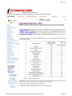
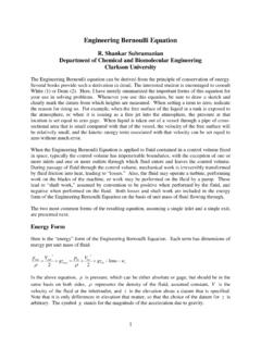
4 If the riser is properly sized to maintain velocity, adding a trap only increases the suction- line pressure risers are unnecessary. The steps of unloading for commercial Trane units with scroll compressors are such that a single, carefully selected riser can maintain oil circulation at any load the most careful installation allows foreign matter into the system . That s why it s critical to install suction filters and properly maintain them. Once cleanup is complete, a fresh core should Figure 1 Recommended Suction- line Arrangements From Evaporator HeadersTo compressor located above evaporatorEvaporator headers join at a point lower than the lowest suction header outletTo compressor located below evaporatorHeight of common riser exceedsheight of evaporatorprevent any refrigerant that condenses in the suction line from flowing to the compressor when the unit is suction- line insulation if moisture condensation and dripping pose a problem, or to prevent refrigerant from condensing inside the lines if long runs will be exposed to low t install suction lines underground.
5 The likelihood of corrosion, vibration, condensation of water outside and refrigerant inside the line , combined with inaccessibility, make this practice unwise. If underground installation is unavoidable, make provisions to insulate, waterproof and encase the lines in a hard line . Sufficient subcooling must be maintained at the expansion valve. To provide proper operation throughout the range of operating conditions, the liquid- line pressure drop should not exceed the unit s minimum subcooling value less 5 F. To achieve this objective, keep these liquid- line considerations in mind:nSelect the smallest, practical line size for the application. Limiting the refrigerant charge improves compressor installed in the shell to prevent oil 1 illustrates one method of trapping the evaporator coil. The suction lines from the evaporator headers should join at a point lower than the lowest suction header outlet.
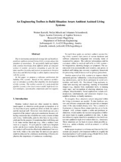
6 This arrangement drains the coils and prevents oil and refrigerant from backfeeding from one coil to the other(s).The common connection should then rise above the height of the coil before proceeding to the compressor to prevent the refrigerant and oil in the evaporator from free-draining into the suction a 1-inch pitch toward the evaporator for every 10 feet of run to Table 1 Minimum Suction- line VelocitiesFor Oil EntrainmentNominalPipe Size, Velocity, fpmRiserHorizontal1-1/87005251-3/8780585 1-5/88406302-1/89807352-5/810808103-1/81 180885 providing insights for today s HVAC system designer 3nnWhen designing the liquid line for a typical air-conditioning application ( one with an operating range of 40 F to 115 F), remember that every 10 feet of vertical rise will reduce subcooling by F, while every 10 feet of vertical drop will add F of one expansion valve per distributor.
7 An expansion valve serving more than one distributor will distribute the refrigerant a 1-inch pitch toward the evaporator for every 10 feet of run. Since this pitch equals that of the suction line , the two may be run the system is designed with a liquid line rise, a column of liquid refrigerant remains atop the volume of refrigerant gas in the condenser whenever the unit stops. The liquid refrigerant will eventually drain down the line and may fill the condenser .. perhaps even overflow to the compressor. Sloping the liquid line toward the evaporator creates a gas trap at the line s highest point, preventing liquid refrigerant from valves are required. They prevent liquid refrigerant from filling the evaporator when the compressor stops and slugging when the compressor restarts. Adding solenoid valves also prevents siphoning which could allow an elevated column of liquid to overcome the gas trap and flow back into the condenser and the liquid line must be routed through an area warmer than outdoor air temperature, insulate the line to prevent the refrigerant from sure to include a replaceable-core filter drier to permit proper system cleanup and moisture removal.
8 The core should be changed whenever the system is opened for adding a moisture-indicating sight glass to permit a visual check of the liquid column for bubbles. However, never use the sight glass to determine whether the system is properly charged! Instead, either charge the system based on the required subcooling or calculate the amount of refrigerant needed and add it based on line . Limit the pressure drop in the discharge line to 6 psid whenever possible to minimize the adverse effect on unit capacity and efficiency. While a pressure drop of as much as 10 psid is usually permissible, note that a 6-psid pressure drop reduces unit capacity by percent and efficiency by 3 design the discharge line properly, follow the guidelines recommended below:nChoose the shortest route from the compressor to the different pipe sizes for horizontal and vertical lines to make it easier to ,W V SUXGHQW WRDYRLG KRW JDV E\SDVV LQ FRPIRUW FRROLQJ DSSOLFDWLRQV HVSHFLDOO\ WKRVH ZLWK YDULDEOH DLU YROXPH 9$9 V\VWHPV match line pressure drop and refrigerant velocity to discharge- line assure proper oil entrainment and avoid sound transmission, size the discharge line so that refrigerant velocity equals or exceeds the minimum velocity in Table 2 and remains below 3,500 oil and condensed refrigerant from flowing back into the compressor during off cycles by: (a) pitching the discharge line toward the condenser and (b) routing the discharge line so that it rises to the top of the condenser, then drops to the level of the condenser inlet, creating an inverted risers are unnecessary.
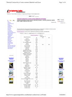
9 The scroll compressors in current Trane commercial units unload to the extent that a single, properly sized riser can transport oil at any load traps are also unnecessary. Avoid using riser traps. If the discharge riser is sized to maintain the proper refrigerant velocity, adding a trap will only increase the pressure Gas Bypass line . Hot gas bypass (HGBP) describes the refrigerant system design historically used to provide stable operation at low loads while avoiding coil freeze-up and compressor cycling problems. When the load falls below the compressor s minimum stage of loading, the modulating HGBP valve attempts to maintain suction pressure by Table 2 Minimum Discharge- line VelocitiesFor Oil EntrainmentNominalPipe Size, Velocity, fpmRiserHorizontal7/83752851-1/84303251- 3/84803601-5/85203902-1/8600450n4 ENEWS-27/4A publication ofThe Trane CompanyWorldwide Applied Systems GroupLa Crosse, WI 54601-7599 Printed on recycled paper as part ofThe Trane Company s recycling hot gas from the compressor discharge to the evaporator strategy reduces the system s cooling capacity since the diverted refrigerant bypasses the evaporator.
10 It also increases compressor energy consumption significantly and can cause unstable operation if improperly s good design practice to avoid hot gas bypass for comfort cooling applications, particularly those with variable-air-volume (VAV) other types of applications, observe these guidelines:nSize the HGBP line to carry only the desired amount of gas at a pressure drop equalling the sum (usually 20 to 40 psid) of the pressure drops for the discharge line plus the condenser and subcooler plus the liquid line . Oversizing the line can cause the HGBP and thermal expansion valves to hunt. nTo assure proper oil entrainment, size the HGBP line so that refrigerant velocity equals or exceeds the minimum velocity recommended in Table the HGBP valve above the discharge line and the distributor inlet to promote free drainage away from the HGBP valve and toward the distributor or discharge the HGBP line to prevent the refrigerant from condensing during low line .