Transcription of ASCO Valve 8040 and 8215 aluminum body …
1 Direct Acting or Piloted 2/2. 4 SERIES. 2-WAY. aluminum body Solenoid valves 8040. 1/8" to 3" NPT. 8215. Features Lightweight, low-cost valves for air service % ^ # ). Ideal for low pressure applications Provides high flow, Cv up to 138 (Kv 118). Air and vacuum service Construction Valve Parts in Contact with Fluids body aluminum Seals, Diaphragms, Disc NBR. Disc-Holder PA ( and watt Normally Open only). Core Guide CA. Core Tube 305 Stainless Steel Rider Rings PTFE. Core and Plugnut 430F Stainless Steel Springs* 302 Stainless Steel Shading Coil Copper NC. * For 8040H006, 8040H007, 8040H008, spring material is 17-7 PH. Electrical NO. Watt Rating and Power Consumption Spare Coil Part No. Standard Coil and AC General Purpose Explosionproof Class of DC VA VA. Insulation Watts Watts Holding Inrush AC DC AC DC. F - 16 40 238210 - 238214 - F 25 70 238610 238710 238614 238714. B - - - - 62691 - - F - 27 160 99257 - 99257 - F - 50 385 206409 - 206409 - Standard Voltages: 24, 120, 240, 480 volts AC, 60 Hz (or 110, 220 volts AC, 50 Hz), 8040.
2 6, 12, 24, 120, 240 volts DC. Must be specified when ordering. Other voltages available when required. (Note: 24 volt AC, 60 Hz not available with watt coil). Approvals: CSA certified to: Solenoid Enclosures Standard: RedHat II - Watertight, Types 1, 2, 3, 3S, 4, and 4X; RedHat - Type I. 8040 Series: 1) Standard No. 139 "Electrically Operated Optional: RedHat II - Explosionproof and Watertight, Types 3, 3S, 4, 4X, 6, valves ," File 10381. 6P, 7, and 9; RedHat - Explosionproof and Raintight, Types 3, 7, and 9. 2) Automatic Gas valves ( ), File 112872. (Except EF8215A40 and EF8215A90, which are suitable for Types 3 and 7. (C and D) only and have a T2B temperature rating code.) 3) Automatic Gas Safety Shutoff valves C/I ( ), To order, add prefix EF to catalog number. File 112872. See Optional Features Section for other available options. 8215 Series Normally Closed: 1) Standard No. 139 "Electrically Operated Nominal Ambient Temp. Ranges valves ," File 10381. 2) Automatic Gas valves ( ), File 112872.
3 AC DC. 8215 Series Normally Open: Series RedHat II/RedHat RedHat II RedHat 1) Standard No. 139 "Electrically Operated -40 F to 125 F. 8040 - - valves ," File 10381. (-40 C to 52 C). 32 F to 77 F UL listed, as indicated. FM approved (Normally Closed 32 F to 125 F 32 F to 104 F only, except Catalog Numbers 8215A090 and 8215A040). 8215 (0 C to 25 C). (0 C to 52 C) (0 C to 40 C). (104 F/40 C occasionally) RedHat II meets applicable CE directives. Refer to Engineering Section for details. Refer to Engineering Section for details. 8040_8215R2 7. 2/2. SERIES. 4. 2-WAY. 8040. 8215. Specifications (English units). Operating Pressure Max. Watt Rating/. Differential (psi) Fluid Const. Class of Coil Max. AC Max. DC Temp. F aluminum body Ref. Insulation . Pipe Orifice Cv Gas Size Size Flow Capacity Air-Fuel Air-Fuel UL . (ins.) (ins.) Factor Btu/hr Min. Gas Gas AC DC Catalog Number AC DC Listing AC DC. NORMALLY CLOSED (Closed when de-energized). 1/8 5/16 53,700 0 15 - 125 - 8040H006 11 - 1/4 5/16 59,000 0 15 - 125 - 8040H007 11 - 3/8 5/16 64,400 0 15 - 125 - 8040H008 11 - 3/8 3/4 183,000 0 50 25 125 104 8215G010 2 3/8 3/4 - 5 125 125 125 104 8215G001 1 1/2 3/4 291,000 0 2 - 125 - 8040G022 13A - 1/2 3/4 238,500 0 50 25 125 104 8215G020 2 1/2 3/4 - 5 125 125 125 104 8215G002 1 3/4 3/4 512,000 0 2 - 125 - 8040G023 13B - 3/4 3/4 247,500 0 50 25 125 104 8215G030 4 3/4 3/4 - 5 125 125 125 104 8215G003 3 1 1 5/8 21 1,119,000 0 25 25 125 77 8215B050 6 16 1 1/4 1 5/8 32 1,730,000 0 25 25 125 77 8215B060 6 16 1 1/2 1 5/8 35 1,900,000 0 25 25 125 77 8215B070 6 16 2 2 3/32 60 3,251,000 0 25 15 125 77 8215B080 7 17 2 1/2 3 117 5,821,000 0 5 - 125 - 8215A090 8 - 3 3 138 7,430,000 0 5 - 125 - 8215A040 8 - NORMALLY OPEN (Open when de-energized).
4 3/8 3/4 172,500 0 125 125 125 104 8215G013 9 1/2 3/4 4 206,250 0 125 125 125 104 8215G023 9 3/4 3/4 247,500 0 125 125 125 104 8215G033 10 1 1 5/8 22 1,191,750 0 25 15 125 77 8215C053 12 18 1 1/4 1 5/8 33 1,793,250 0 25 15 125 77 8215C063 12 18 1 1/2 1 5/8 37 1,988,250 0 25 15 125 77 8215C073 13 19 2 2 3/32 58 3,100,000 0 25 15 125 77 8215C083 14 20 2 1/2 3 117 6,290,000 0 5 - 125 - 8215B093 15 - Do not use for Fuel Gas. On 50 hertz service, the watt rating for the solenoid is watts. FM Approved Process Control valves . See Engineering Section (Approvals) for details. Type I enclosure only. = Safety Shutoff Valve ; = General Purpose Valve . Refer to Engineering Section (Approvals) for details. 1" Drop @ 2" Inlet Pressure, 1,000 or more, Specific Gravity Gas. Not available with 24 volt, 60 Hz coil. 8 8040_8215R2. 2/2. SERIES. 4. 2-WAY. 8040. 8215. Specifications (Metric units). Operating Pressure Max. Watt Rating/. Differential (bar) Fluid Const. Class of Coil Pipe Orifice Kv Flow Gas Max.
5 AC Max. DC Temp. C aluminum body Ref. Insulation . Size Size Factor Capacity Air-Fuel Air-Fuel UL . (ins.) (mm) (m3/h) Btu/hr Min. Gas Gas AC DC Catalog Number AC DC Listing AC DC. NORMALLY CLOSED (Closed when de-energized). 1/8 .86 53,700 0 - 52 - 8040H006 11 - 1/4 .94 59,000 0 - 52 - 8040H007 11 - 3/8 64,400 0 - 52 - 8040H008 11 - 3/8 19 183,000 0 52 40 8215G010 2 3/8 19 - 52 40 8215G001 1 1/2 19 291,000 0 - 52 - 8040G022 13A - 1/2 19 238,500 0 52 40 8215G020 2 1/2 19 - 52 40 8215G002 1 3/4 19 449,000 0 - 52 - 8040G023 13B - 3/4 19 247,500 0 52 40 8215G030 4 3/4 19 - 52 40 8215G003 3 1 41 18 1,119,000 0 52 25 8215B050 6 16 1 1/4 41 27 1,730,000 0 52 25 8215B060 6 16 1 1/2 41 30 1,900,000 0 52 25 8215B070 6 16 2 53 51 3,251,000 0 52 25 8215B080 7 17 2 1/2 76 100 5,821,000 0 - 52 - 8215A090 8 - 3 76 118 7,430,000 0 - 52 - 8215A040 8 - NORMALLY OPEN (Open when de-energized). 3/8 19 172,500 0 52 40 8215G013 9 1/2 19 206,250 0 52 40 8215G023 9 3/4 19 247,500 0 52 40 8215G033 10 1 41 19 1,191,750 0 52 25 8215C053 12 18 1 1/4 41 28 1,793,250 0 52 25 8215C063 12 18 1 1/2 41 32 1,988,250 0 52 25 8215C073 13 19 2 53 50 3,100,000 0 52 25 8215C083 14 20 2 1/2 76 100 6,290,000 0 - 52 - 8215B093 15 - Do not use for Fuel Gas.
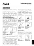
6 On 50 hertz service, the watt rating for the solenoid is watts. FM Approved Process Control valves . See Engineering Section (Approvals) for details. Type 1 enclosure only. = Safety Shutoff Valve ; = General Purpose Valve . Refer to Engineering Section (Approvals) for details. 1" Drop @ 2" Inlet Pressure, 1,000 or more, Specific Gravity Gas. Not available with 24 volt, 60 Hz coil. 8040_8215R2 9. 2/2. SERIES. 4. 2-WAY. 8040. 8215. Dimensions: inches (mm). Const. Const. Ref. 1-4, 9, 10, 13A, 13B. Ref. H K L P W 1/2 NPT. ins. 1. mm 87 51 70 73 63 P. ins K H. 2. mm 102 63 70 88 63. ins. NPT. 3 BOTH ENDS. mm 98 56 84 77 59. ins. L W. 4 FLOW. mm 113 68 84 92 59. [42]. ins. 6 2 MOUNTING HOLES. mm 174 108 127 142 137 .28 [ ]. ins. 7 . mm 190 115 155 151 160. ins. Const. Ref. 6, 7, 8, 16, 17. 8 . mm 260 146 198 201 202. ins. 7/8 DIA HOLE. 9 FOR 1/2 CONDUIT. CONN. mm 112 69 70 98 60. ins. 10 P. mm 123 69 84 103 60. H K. ins. 11. mm 69 36 51 58 43. ins. 12. mm 174 56 127 92 137 NPT. BOTH ENDS.
7 Ins. 13. mm 174 55 127 90 137 L W. FLOW. ins. 13A. mm 103 63 70 87 62. Const. Ref. 11. ins. 13B W. mm 114 67 84 92 61 1/2 NPT. ins. 14 . mm 189 61 155 97 160 2 CORED HOLES P..350 [ ] DEEP FOR H. ins..164-32 TH'D. K. 15 FORMING SCREW. mm 260 78 198 133 202 .60 [15] NPT. BOTH ENDS. ins..800 [ ]. 16 R .088 [R ] .90 [23] .250 [ ]. mm 193 102 127 161 137 .406 [ ] 4 PLACES. IN. ins. 17 .115 [ ] 2 PLACES .97 [25]. mm 208 111 155 170 160 BOTTOM VIEW OF body ..750 [ ]. L. ins. FLOW. 18. mm 156 53 127 112 137. 19. ins. Const. Ref. 12-15, 18-20. mm 193 52 127 110 137. L. ins. 20. mm 58 155 117 160 .88 [ 22]. HOLE FOR. 1/2 CONDUIT. IMPORTANT: valves may be mounted in any position CONN. except all DC constructions and those marked , which P. must be mounted with the solenoid vertical and upright. Constructions marked must be mounted with the H. solenoid vertical and upright or horizontal only. NPT. BOTH ENDS. W. FLOW. 10 8040_8215R2.