Transcription of ASEAN Life Sciences Conference and Exhibition - …
1 1 CRITICAL UTILITY DESIGN AND MAINTENANCE Gaston Loo Maintenance Lead MSD SINGAPORE ASEAN life Sciences Conference and Exhibition - 2013 2 Type of utilities system Regulatory requirement Design approach Design principle and strategic GEP System boundaries Maintenance plan Rouging Filter integrity testing Contamination / microbial control Industry trend - PAT Agenda 3 Critical utilities system Gas system Pure steam Water system Non-critical utilities system Chilled water Plant steam Instrument air Potable water Type of utilities system 4 Critical utilities system Direct impact system (process system) Contact the product Direct impact product quality Contact materials that ultimately become part of product Depend on process, can be raw material, component or process aid (excipient) Application example: N2 for vessel blanketing Pure steam SIP WFI for compounding Definition 5 Critical utilities system Equipment that use critical utility.
2 Blow-fill-seal (BFS) packaging machines Compounding system Filling line Freeze-drying (lyophilization) Part washer Autoclave SIP skid 6 Gas system Critical utilities system Nitrogen Storage tank Distribution loop Sterile air (filtered air) Generation (compressed air) Oil free type Distribution loop Buffer tank Air dryer filter 7 Pure steam Critical utilities system Pure steam Generation Distribution loop Key feature Feed water from PFW Use plant steam for distillation process - Removal of endotoxins and other impurities via multiple separation stages - For process sterilization purpose 8 Critical Utilities System Water For Injection (WFI) Generation Feed water from PFW Storage and distribution Water system Purified water system (PFW) Generation Storage and distribution 9 Storage and Distribution System Key components Tanks Pumps Heat exchangers Valves Sample Valves Instrumentation What s critical?
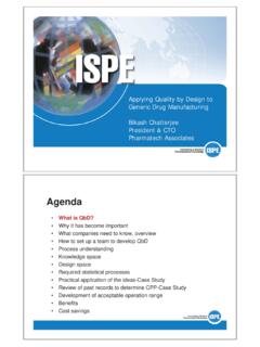
3 Location 10 Schematic PFW Generation UNIT MULTIMEDIA FILTER DOSING HYPOCHLORITE FILTER CARBON FILTERS CARTRIDGE TO PURIFIED WATER TANK HEAT HEAT EXCHANGERS COOL REVERSE OSMOSIS TWIN PASS CONTINUOUS DEIONISATION STORAGE TANK PUMP RETURN FROM PURIFIED WATER TANK UNIT SOFT WATER INLET FINAL FILTER 11 PFW Generation The softened and chlorinated water is fed to a multi-media filter unit (MMF). Remove particulate present within the feed water supply. After filtration, the water flows to a break tank for storage. Multi-media filter 12 Break tank PFW Generation Feeds into break tank The MMF water Water re-circulated back from final filter The It consist of spray ball heated vent filter bursting disc level sensors 13 PFW Generation The activated carbon filter removes light weight organics any residual chlorine Daily backwash cycle (Auto or manual) Activated carbon filter 14 Reverse Osmosis (RO) unit PFW Generation To remove up to 90 - 98% of inorganic ions together with all large contaminants and organic molecules contained in the feed water.
4 A twin pass RO unit protect the system from bacteria and pyrogens. 15 PFW Generation - RO permeate is fed to the CDI unit for polishing. - Uses high purity resins materials to remove all ionic materials from the water effectively. - Give a maximum resistivity of :-cm (25oC). Continuous Deionisation (CDI) Unit 16 Water quality PFW Generation 1 1 5 10 100 5 10 Micro-siemens/cm S/cm@25oC Mega-ohms/cm M:/cm@25oC USP 29 Conductivity < PS/cm at 25 C TOC < 500ppb ( mg/l) PFW 17 Conductivity of different water PFW Generation Pure water Purified water Drinking water Brackish water Sea water Conductivity S/cm 0. 1 10 100 1000 10000 100000 LOW MEDIUM HIGH Resistivity M /cm 100 10 18 PFW Generation The water is passed through m before entering into storage tank.
5 Bioburden reduction Removal of particulate contamination down to m. Final Filter Microbio limits: - drinking water < 500 cfu/ml - PFW < 100 cfu/ml - WFI < 10 cfu/ml 19 Type of utilities system Regulatory requirement Design approach Design principle and strategic GEP System boundaries Maintenance plan Rouging Filter integrity testing Contamination / microbial control Industry trend - PAT Agenda 20 What might a regulator want? For people to understand the intent of regulations, and then implement programs to meet that intent. 21 FDA Regulatory requirement FDA has recently focused attention on critical utilities. End users and their qualification and quality assurance personnel must demonstrate that the facility complies with 21 CFR (a) which states: Equipment shall be constructed so that surfaces that contact components, in-process materials or drug products, shall not be reactive, additive, or absorptive so as to alter the safety, identity, strength, quality, or purity of the drug product beyond the official or other established requirements.
6 22 PIC/S Regulatory requirement PIC/S is the abbreviation and logo used to describe both the - Pharmaceutical Inspection Convention (PIC) - Pharmaceutical Inspection Co-operation Scheme (PIC Scheme) PIC Scheme PIC Scheme Convention An informal arrangement A formal treaty Has no legal status Has legal status Between Health authorities Between countries Exchange of information Mutual recognition of inspections The main differences between the PIC Scheme and PIC are : operating together in parallel. 23 PIC/S Regulatory requirement PIC/S develop guidance The Aide-Memoire Inspection of Utilities for GMP inspectors For training and preparation of inspection Checklist for critical utility on water, steam and gases 24 Standard Regulatory requirement Improved standard and guidelines such as - ASME Bioprocessing Equipment standard (BPE-2012) - ISPE Baseline@ Pharmaceutical Engineering Guides - International Standard ISO 8573 Compressed Air have driven the quest of quality in pharmaceutical industry.
7 Vary of interpretation by different regulators 25 EMEA Regulatory requirement Reflection Paper on 5 March 2008 EP requirement for WFI be produced only by distillation Refer RO membranes as "bacterial fermenters" and production of WFI RO would not be as safe as water prepared by distillation Mandatory for manufacture of all products shipped into the European Economic Area EMEA reaffirms rejection of RO for WFI production in EEA 26 USP Regulatory requirement Recognized and used in > 140 countries Guide to produce medical products Specify standard for PFW and WFI Pharmacopeia Example: Conductivity @ temperature (USP <645>) TOC (USP <643>) Bacteriological Purity Total Aerobic Count (CFU/Ml) 27 Type of utilities system Regulatory requirement Design approach Design principle and strategic GEP System boundaries Maintenance plan Rouging Filter integrity testing Contamination / microbial control Industry trend - PAT Agenda 28 GEP Design approach Design approach affect by following factors.
8 Factors Critical Utility Design Process Budget Timeline Quality Validation Safety & Environment Automation Feed Water Quality Specification 29 Design and project workflow Direct-impact systems only Quality-critical requirements only Design principle and strategic 30 GEP Set the standard and specifies your requirements Document the functions you want Used as a live document up until the DQ is completed and approved Traceability of PQ and OQ functionality testing (RTM) Part of procurement process tender document URS User requirement specification 31 Design phase Engineering specification FDS - Functional Design Specification HDS - Hardware Design Specification SDS - Software Design Specification DQ - Design Qualification Owner Vendor 32 GEP Risk assessment Minimize project expenditures, streamline validation.
9 And forgo unnecessary processes or mechanical design options Serve to qualify the use of certain system and component attributes that affect cost and performance Determine what operations of critical utilities classified as critical and non-critical Determine the scope and extend of validation Objective 33 GEP Risk assessment tool Failure Mode Effects Analysis Assessment tool to determine their potential value for process design techniques Cause & effect analysis Assign each risk 1-10 for occurrence / severity / detection RPN = Occurrence x Severity x Detection FMEA 34 GEP Risk assessment tool Example: Microbial development in the WFI storage tank - Surface finish on tank < 20 (Ra) - Temp > 80 oC With rating 0-10: RPN = O X S X D = 1 X 10 X 2 = 20 (low risk) FMEA Design specs 35 FMEA form Risk Assessment & FMEA Risk Assessment FMEA Structured by System Quality Attributes (SQA) Structured by process steps Begins with identifying hazards to SQA s Begins with identification of potential failure modes Controls are assessed based on design features and procedures Controls are grouped as prevention and detection controls Used to identify controls that must be incorporated into the user requirements Used to identify and prioritize risks of a given process Used to establish acceptance criteria for validation 36 37 Good Engineering Practice (GEP) I don t know how to explain them, but I know them when I see them.
10 38 GEP Apply to all critical utility from design to operation stage: Projects design construction commissioning Standards & Practices drawing control equipment change management documentation Operations maintenance calibration safety and environmental Scope Good Engineering Practice (GEP) 39 General rule Good Engineering Practice (GEP) Allow provision for future expansion Utilities should be routed from plant room to process area Process utility systems are designed to satisfy the requirement of facility Meet regulatory requirements and expectations pertaining to equipment Drawing for utility systems must be approved and updated. 40 Good Equipment Layout Good Engineering Practice (GEP) Keep design as simple as possible Ease of access for operation and maintenance Follow process flow Provide good spacing for equipment Operators review equipment layout during design stage Equipment and piping labeling Good Engineering Practice (GEP) System Qualification Drawing requirements: yshow the plant layout, with service connections and, as appropriate: yAll isolating-, drain-, vent-, control-valves, and items served, complete with tag numbers where used.