Transcription of Assembly & Operation Instructions - Bessler
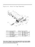
1 STAIRWAYCOMPANYA ssembly & Operation InstructionsModels 30, 40 & 70 Bessler Assembly & OperationInstructions For Models 30, 40 & 70 Stringers (2)TreadsHandrailHandrail PostsHeader Guide FrameSlide BarsSpring Drum AssembliesDoor DrumStringer DrumPulleysDoor Guide FrameSlide CablesStringer CablesStringer Cable Holders (2)Catch LockDoorOffset Piano HingePull ChainTop Tread (7-1/4")Ladder RodsShipping Fork is for holdingcables during List55a7820*Appearance of parts may vary slightly according to specific You make sure you receive the best performance fromyour Bessler , please take a few moments to familiarizeyourself with all of the parts and guidelines. Seekprofessional help if not experienced in : An experienced finish carpenter with goodhelp should easily install the door jamb and stairsand adjust for Operation in four hours or less. Timeis directly dependent on skill and the understandingof these Instructions .
2 This is a stairway; take yourtime, work safe and eliminate Opening Dimensions (E)The Bessler Stairway will work with almost anyceiling thickness of 6-1/4" or more. If more than14", call factory for additional Instructions . ReviewFigure 1 and refer to Table 2 to make sure the sizeof the rough and finished openings are correct foryour specific 1 EBCADTABLE 1 Size1234567(A)Floor ToFloor7'7" 7'10"7'11" 8'4"8'5" 8'10"8'11" 9'4"9'5" 9'10"9'11" 10'4"10' 5" 10'10"(B)RadiusAbove4'1"4'8"5'3"5'10"5'1 0"6'6"7'1"(C)PlumbHeight2'11"3'5"3'11"4' 5"4'6"5'1"5'5"(D)RunBelow5'4"5'8"6'0"6'4 "6'8"6'11"7'4"Check Model SizeBe sure to check the Plumb Height (C) and RadiusABOVE (B) the header. Review Figure 1 above andrefer to Table 1 to make sure the size of your specificmodel fits within the specified PartsYou should have three cartons:Carton No. 1 Hardware, fasteners, treads, ladderrods and these No.
3 2 Door with offset piano hingeattached (do not remove) and is predrilled formounting the Door Guide No. 3 Two stringers, one handrail andhandrail all parts against the Parts List on Page : FINISHED JAMB OR CLOSING JAMB ANDDOOR STOPS ARE NOT PROVIDED BY Bessler .#10 x 1" Screws#10 x 1-1/4" Screws3/16" x 2" Eye Bolt w/Nut1" Ladder WashersDoor Panel ChainDoorChainPullRing1/4" X 1-1/4" Screw And Lock Nut#10 Hex NutsLadder RodsModels 30 & 40: 17-5/16"Model 70: 19-1/4"Model#30 sizes 1 4#30 sizes 5 7#40 sizes 1 4#40 sizes 5 7#70 sizes 1 4#70 sizes 5 7 RoughOpeningInside " x 5'6"22-1/2" x 6'0"2'2" x 5'8"2'2" x 6'2"2'8" x 5'8"2'8" x 6'2"FinishOpeningInside " x 5'6"22-1/2" x 6'0"2'0" x 5'6"2'0" x 6'0"2'6" x 5'6"2'6" x 6'0"Guide FrameSlide BarInside Width16-5/8"16-5/8"16-5/8"16-5/8"18-7/16 "18-7/16"TABLE 1 Models 40 & 70 Prepare the rough opening to the size shown inTable 2 for the model and size of your stair.
4 Doubleheaders may be needed in certain standard carpentry practices when buildingrough opening and check your local building codefor correct construction for perpendicular and parallel 3 Models 40 & 70 After sized correctly and squared, secure jamb bynailing slats across the four corners, allowing slatsto overhang jamb edges. Lift into ceiling and allowto hang from attic floor by the slats. Fasten securelyto ceiling joists with 16 penny or larger nails or 1/4x 3" or larger lag screws. Remove slats. Trim dooropening on ceiling using standard materials Model 30 is specially designed to fit between24" on center truss ceilings. The rough and finishedopening will be the same, provided the trusses areplaced on 24" centers. This stair is designed to beinstalled in ceilings that are a minimum of 6-1/4"and maximum of 15" in depth. If the truss cord ismade from 2 x 4's, you will have to shim the cordto a minimum depth of 6-1/4", making certain thatall four corners of the finished opening are square(90 ).
5 Trim door opening on ceiling using standardmaterials and 30 Proceed to Step Instructions for Model 30 varies slightly fromModels 40 & 70 in the preparation of the sure of the model you are installing and followappropriate 1 MODEL 30 ONLYS teps 1-3 MODELS 40 & 70 ONLYStep 2 Models 40 & 70 NOTE: Jamb is not furnished by Bessler Table 2 on page 3 for dimensions for yourmodel and size. Build the finished jamb on theground. Finished jamb should be constructed from1" dressed lumber (depth will vary depending onceiling thickness). Depth of jamb should be suchthat it fits flush with ceiling and attic FlooringCeiling MaterialFinishJambStopTrimCheck Guide Frame Slide BarsCheck Header Guide Frame (#5) and Door GuideFrame (#10) Slide Bars for alignment. The Models30 & 40's slide bars should be 16-5/8" inside toinside and parallel to each other. Model 70 shouldbe 18-7/16". You may adjust the slide bars bybending the bracket slightly in or out if Guide FrameDoor Guide FrameSlide BarsPreparation Of The Rough OpeningPreparation Of The Rough OpeningPreparation Of The Finished 5 Install 3/8" x 1-1/4" door stops (not supplied) onremaining three sides at 1-3/8" from bottom.
6 Doorstop may need to stop at Spring Drum Assembliesor be trimmed to allow placement of Spring DrumAssemblies in steps 6 and 4On selected header, draw a line 1-5/8" up from thebottom of the door jamb. Then, approximately 2inches from each corner, partially drive 2 small nailson this line for a guide. Hold Door Panel (#15)upright with the loose leaf of the offset piano hingeagainst the nails. Center the door panel in thefinished jamb, predrill two holes and drive two 1"screws to hold the door. Now check the swing ofthe door to make sure it does not bind in the finishedjamb. Make adjustments in the jamb as screws in the remaining three holes andremove 2 positioning nails. Make sure screw headsare screwed in 2 Steps 4 11 2"2"1-5/8" 1-3/8"Step 4 Step 5 Step 5 Step 6 Step 7 Step 8 Step 9 Step 10 Step 11 HeaderNOTE: Jamb &Stops Not SuppliedBy Bessler NOTE: Right and left sides aredetermined by standing at bottomof stairs and looking up towardheader.
7 Right and left sides aremirror opposite of each other. 20" 20"20" Header HeaderStep 9 Mount the right side Small Pulley (#9) so that itscenterline is 20" from the well end opposite thedoor and the tab is flush with the attic floor. PREDRILLTHE THREE HOLES AND ATTACH WITH 1" HardwareThe factory has sent two sizes of pan head 1" screws are to be used to attach metal towood. The 1-1/4" screws are to be used to attachwood to wood. DO NOT USE 1-1/4" SCREWS ATTHIS on hand in attic: both Left and Right SpringDrum Assemblies (#6), two Pulleys (#9) and HeaderGuide Frame (#5).Step 6As you face the door, install Right Spring DrumAssembly (#6) in the corner against the selectedheader. There are seven holes in each Spring DrumAssembly.
8 PREDRILL ALL HOLES USING A 1/8" DRILLBIT AND ATTACH WITH 1" SCREWS. LEAVE CABLESALONE FOR 11 Install the Pull Chain (#17) in the door using theeyebolt, #10 x 24 nut, two ladder rod washers andchain. Spread the eyelet just enough to insert theround portion of the chain. Close up the eyelet,then insert eyebolt through 1 washer and a washer on the threaded end and tighten nutwith 3/8" nut driver. You can wait to attach pullring later when you adjust chain for may be a good place to double-check the swingof the door to insure that it doesn't bind againstthe finished 7 Install Left Spring Drum Assembly (#6) in the samemanner as the Right 8 Install the Header Guide Frame (#5) on top of thejamb CENTERED between the Spring DrumAssemblies and SQUARED to the opening. Thereare approximately ten holes in the Guide ALL OF THESE HOLES AND ATTACH WITH1" 10 Mount the left side Small Pulley (#9) in the samemanner as the right Step 12 Lay out stringers on ground or saw horses with theguide channels on the bottom and facing the middle holes at each gain, insert ladderrods through washers and drive through middleholes of both stringers.
9 Place a washer on thethreaded end and run a nut on each ladder roduntil two full threads are showing past the Stringers and Treads:Step 14 Before lifting the stair section,install the Door Guide Frame(#10). "Spring" in the top of thestringers where you left out thetop three treads and insert theDoor Guide Frame Slide Bars(#10a) into the guide channelson the outside of the stringersjust below the riveted top sure the FORKS POINT DOWNand the CATCH PIN is on the leftside of the stringer. Slide theDoor Guide Frame all the wayto the bottom of the stairs. DONOT FORCE as this may spreadthe bars or damage the first, flush the beveled edge with the front of thestringer and make sure the treads are seated all theway into the gains. Then, if needed, try sliding thetreads in or out, front to back, about 1/8" to achievemeasurement. You are working with a pine woodproduct. As you know, pine can vary slightly, evenwhen treads to stringers with four 1-1/4" easy Assembly , drill treads with a 1/8" bit throughthe holes in the stringers.
10 Tighten ladder rod nutsand peen the threaded end of the rods to keep nutfrom coming off. The outside ladder width forModels 30 & 40, should be 17-1/16" 1/32" alongthe length of the stringers. The Model 70 shouldbe 18-7/8" 1/32".ForkCatchPinGuideChannelSlide BarTop StopsSlide BarGuideChannelSpringInwardsStep 13 Spread the stringers apart. The treads are precisioncut to act as spacers to hold the outside width ofthe stairs at a constant measurement and shouldfit snugly into the gains, groove side up. You mayhave to use a mallet to install the treads all the wayinto the gains. Start at the bottom of the stairs andINSTALL ALL BUT THE TOP THREE TREADS. NOTE:THE TOP TREAD IS DEEPER THAN OTHERS. As youinstall the treads, check the outside width of thestairs, both front and back, to maintain the correctmeasurement (See Table 3, Pg. 11). BarSlide BarGuideChannelStopBarTop StopTop StopSpringInwardsStep 16To install the top three treads, have helper pushand hold the stairs up to where their position onthe stringers clears the attic floor.